
A voltage divider is the simplest and most fundamental circuit in electronics. It will be found in any complex electronic circuit. Your task is to recognize this voltage divider and understand how it works. This is what we will talk about in our article.
What the word “divide” means
John had 10 apples and 3 friends: Lucy, Mike and Paul. How can John divide the apples? He can keep one apple for himself and distribute the others to his friends. Is that right? So as not to offend anyone, he could divide three apples for each friend. But they would still have 10 apples in total.
But Paul likes apples very much and Lucy not so much. Lucy gives Paul two of her apples. So Lucy has 1 apple, Paul has 5 apples, Mike also has 3 apples and John has an apple. But we still have 10 apples in total.
The apples can be divided equally or not equally for each participant. No matter how many people we give or how many apples we give, the main thing is that we get as many apples as we had before division.
How to divide the voltage
Let’s remember the previous article about connecting resistors in series. Let me remind you. We had an EMF source and three resistors connected in series.
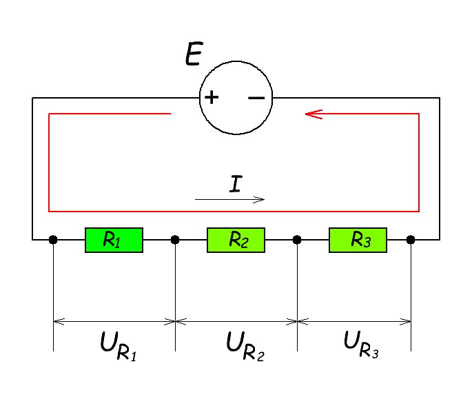
We have a voltage drop across each resistor. In our case:
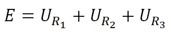
In our example, we have divided the voltage into 3 parts: UR1, UR2 and UR3. Awesome! It’s just like apples! As you can see in this example, the sum of all voltage drops across each resistor equals the source of EMF (E).
In practice, two resistors are most often used.
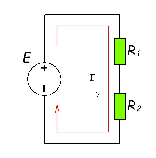
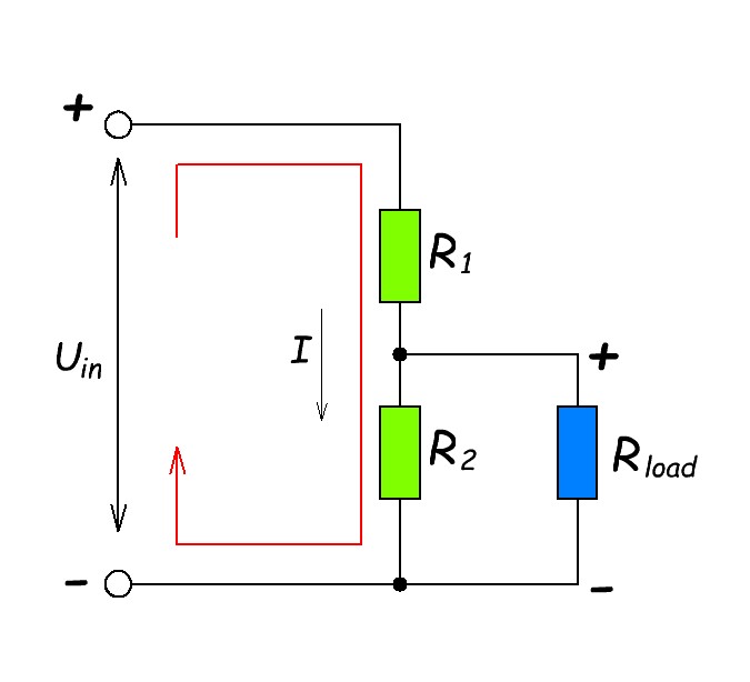
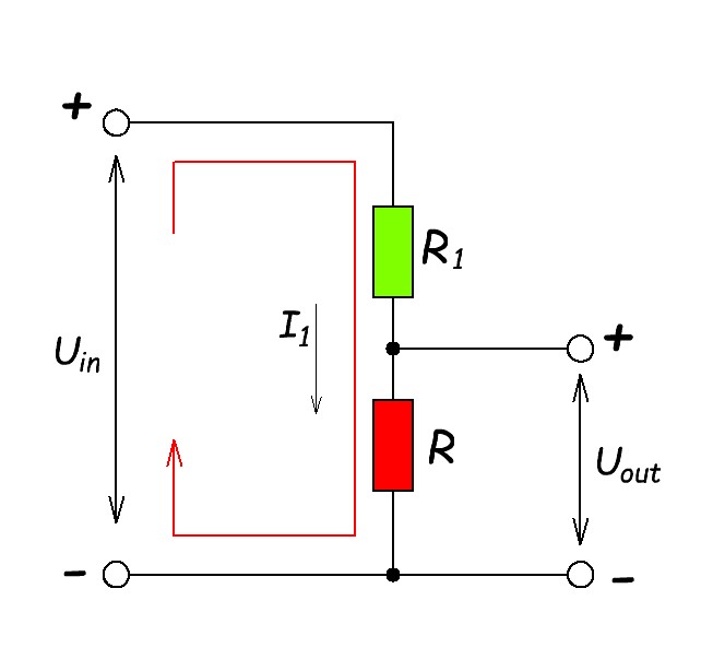
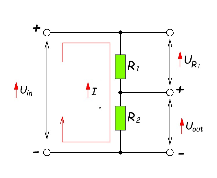
In electronics, circuits are read from left to right. On the left is the input signal and on the right is the output signal. Let’s redraw our wiring diagram for convenience.
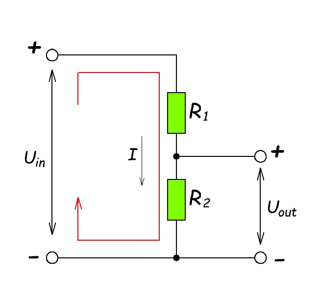
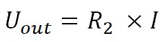
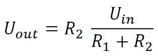
In wiring diagrams, all voltages are measured from the minus supply wire. Therefore, we will measure the output voltage Uout relative to the minus supply. So, we are interested in the voltage drop across resistor R2. How do we find it?
From Ohm’s law:
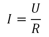
From this expression we need to find the current in the circuit. Again using Ohm’s law.
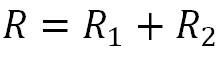
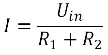
From all of the above, we get
To avoid having to count manually, there is an online calculator where you can calculate any values from this formula.
Voltage divider problems
But there are disadvantages of the voltage divider. So we calculated and got the desired voltage at the output. We want to use this voltage, for example, to power some electronic device. And at this point, we are already in for a disappointment.
Voltage drop across the load and current increase
What happens if we connect a low resistance load to the output voltage of our divider? Rload << R2 .
Here we will see that R2 and the Rload are connected in parallel.
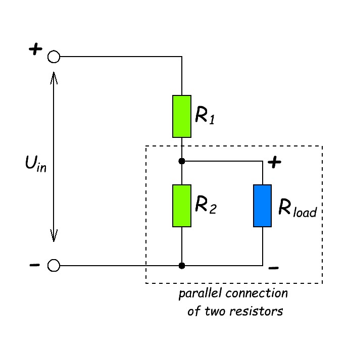
from the formula for the paralleling of resistors:
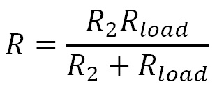
Since we have a load resistance Rload much smaller than R2, this means that their total resistance R will be much smaller than the resistance R2 . R < R2 . Since the resistance in the circuit is less, the current (I) in the circuit will increase. Why? Ohm’s Law and current in series circuit. Let’s call our new current I1 .
R1 + R2 > R1 +R this means that I1 > I.
From the formulas above we get:
UR1 = I1 x R1
but I1 > I
so voltage drop across UR1 increase and
UR < UR1
Power dissipation on a resistor
But there is also another problem that even experienced electronic engineers forget about. After we connected a low resistance load to the output of our voltage divider, we have increased the current in the circuit. Right? At the same moment power dissipation on R1 started to increase. The formula for power dissipation on a resistor looks like this:
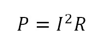
As you may have noticed from the formula, a slight increase in current results in a significant increase in power dissipation. If your resistor is not rated for that much power, it will just burn out.
For example, resistors that are designed for different power dissipation:
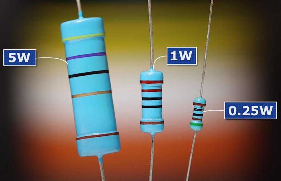
And such resistors have a power dissipation even more than 100 watts.

Therefore, always select the correct resistor power when calculating voltage divider.
Changing the input voltage
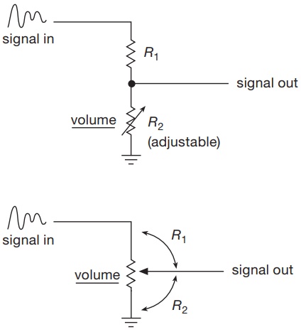
In some cases, input voltage variation is a normal process of circuit operation. For example, changing the volume in the speakers on your computer speakers.
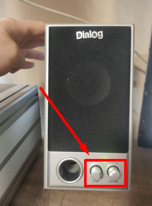
On wiring diagrams, it might look like this:
But there is another case when the input voltage increases or decreases suddenly. How could this all turn out? Let’s look at these two cases:
A) The input voltage (Uin) has increased dramatically.
According to Ohm’s law, we will immediately increase the current in the circuit.
I =U/R , R = R1 + R2
So, the current in the circuit has increased, which means that the voltage drop across each resistor has also increased.
UR1 = IR1 , Uout = IR2
But if we use Uout on a load (Rload) that requires a precise voltage, what happens to the load when the Uout voltage increases very much? The most trivial option is that the load may simply burn out. But if the output voltage (Uout ) is used as a reference voltage for another circuit block, unpredictable results may occur. The circuit will malfunction and operate improperly.
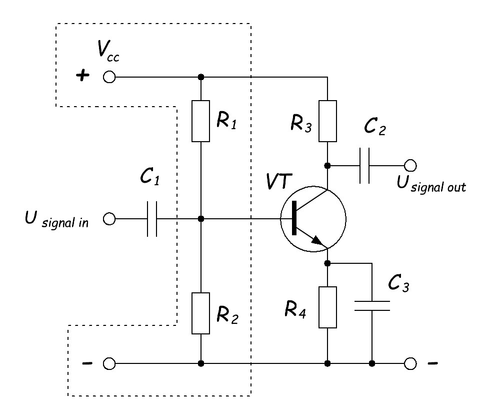
In this diagram, using the dashed line, I have labeled the voltage divider that is used to set the operating mode of the transistor. Changing the voltage Vcc will cause the operating point of the transistor to be biased and the output signal Usignal out out will be distorted. Therefore, in this case it is very important for us that the supply voltage Vcc is stable.
B) The input voltage (Uin) has decreased dramatically.
What would happen in this case?

As the voltage at the input of the voltage divider decreases, the current in the common circuit will also decrease. This means that the voltage drop across each resistor will also drop.
Voltage divider in a battery
What is an ordinary battery? You’ll say it’s a simple voltage source, and you’d be right.
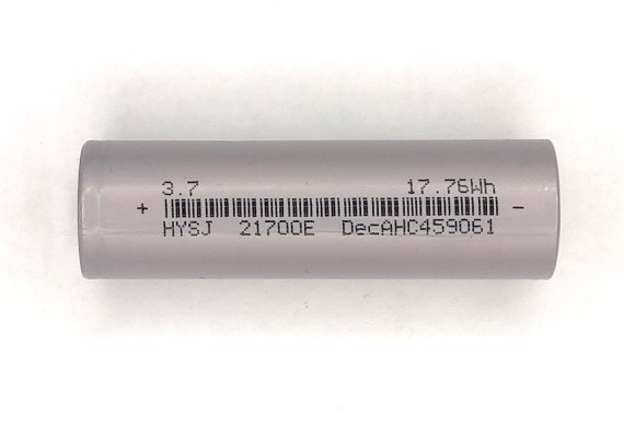
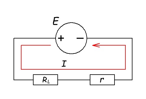
But there’s a little nuance that few people know. Any battery has a resistor in it! What? But how is that possible? Calm down. This is the resistance of the electrolyte, plates and terminals of the battery itself. A practical voltage source has an internal resistance (r) in it .
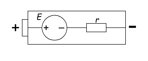
Let’s erase the battery case for clarity.
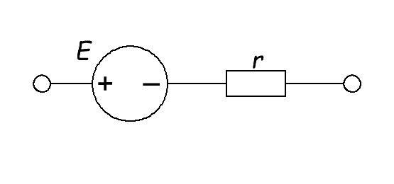
Let’s connect the load (RL). This can be a light bulb, heater, or any other load that is battery powered.
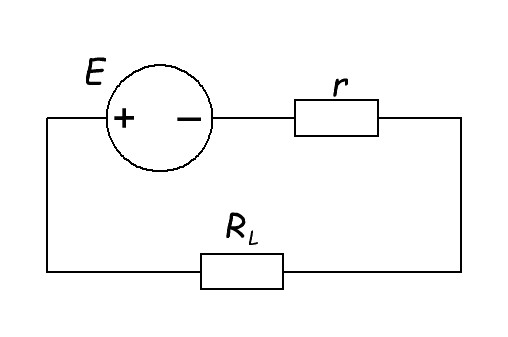
As a result we get a closed circuit. An electric current occurs in a closed circuit.
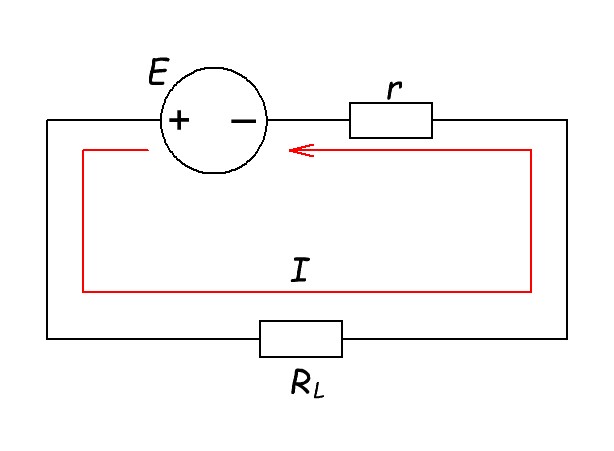
Let’s redraw our diagram for convenience.
And at each resistance we have a voltage drop.
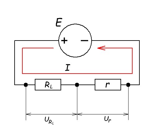
And we have a voltage divider! You can read how to measure and calculate the internal resistance of a battery in this article.