
In electronics, we can divide not only voltage but also current. A current divider is the most fundamental circuit, just like a voltage divider. Once you understand the operation of the current divider and voltage divider, you will be very advanced in your study and understanding of electronics.
Hydraulic analogy
Let’s imagine a pipe that is divided into three different pipes with different diameters and water flows through it. S1, S2, S3 – cross-sectional area. S1<S2<S3.
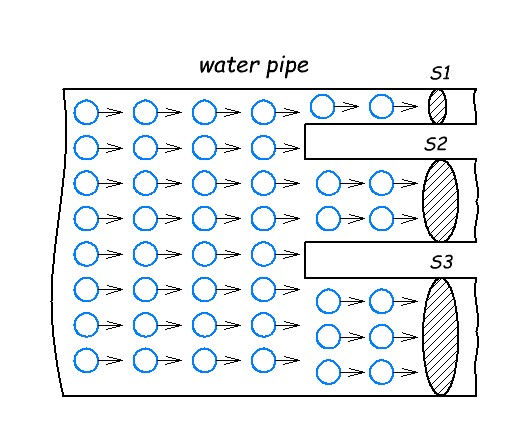
Now we need to remember the current article. What is current, if we consider the analogy of hydraulics? This is the amount of water volume passing through the cross-section of the pipe in one second.
In our case it means that the volume of water for the same time through pipe S1 will be less than through pipes S2 and S3, because the cross-sectional area of pipes S2 and S3 is larger than that of S1. Isn’t that right? And as you remember, the smaller the cross-sectional area, the greater the resistance. This applies to both hydraulics and electronics.
In this case, we divided the water flow from the large pipe into 3 different streams using three different pipes of different diameters. The amount of water flowing into the large pipe is equal to the amount of water flowing out of the three pipes. It’s obvious.
How to divide current
Things are much simpler in electronics than in hydraulics. In our case electric current is a water flow, a big pipe is a common wire, three pipes welded to a big pipe are three resistors with different resistance value.
Let’s look at the simplest example.
E = 10 V, R1 = 10 ohm, R2 = 5 ohm, R3 = 2 ohm
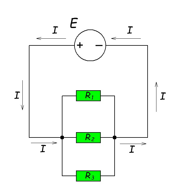
In the hydraulics example, we saw that the greater the resistance of the pipe, the less current flows through it. Let’s look at the operation of this circuit in the simulator.
As you can see, the greater the resistance of the resistor, the less current flows through it. But the interesting thing is that the current in the overall circuit is equal to the sum of the currents flowing through each resistor. It’s exactly like a pipe: the amount of water flowing into a large pipe is equal to the amount of water flowing out of three different pipes. As you can see, the total current in the circuit is 8 Amps. The sum of all currents through the resistors is also 8 Amps (1+2+5). That is, with the resistors, we have taken and divided the total current into three different currents.
You can learn how to calculate the current through each resistor in this article.
Current divider application
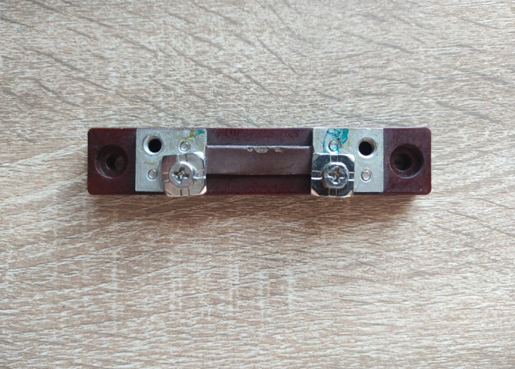
The most common application of a current divider is a shunt and magneto-electric ammeter. A shunt is a low impedance resistor. It looks like this:
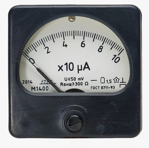
A magneto-electric ammeter looks like this:
Inside, it looks something like this:
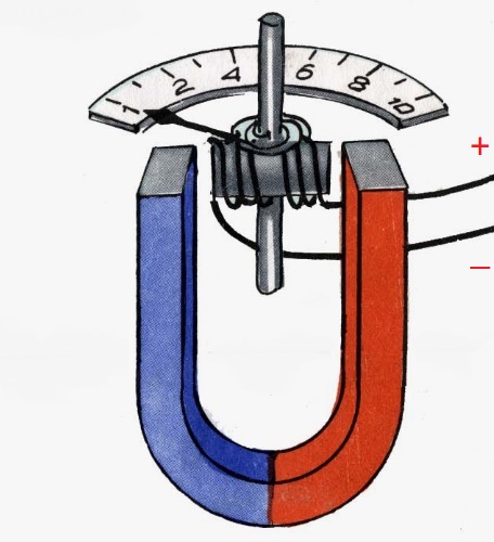
The principle of operation is quite simple: a direct current flows throughs the coil and generates a magnet field, acts against the permanent magnet. The coil twists and moves the pointer.
The coil of the ammeter is wound of several tens of turns of thin copper lacquered wire and has some resistance. A small current is allowed to flow through the coil. Now imagine what happens if a large current passes through the coil? The coil will burn out immediately! Therefore, the ammeter itself can only handle very small currents. But how do we measure a large current with an ammeter that can’t measure a large current? This is where we need a current divider.
We must add a shunt in parallel to the coil of the ammeter.
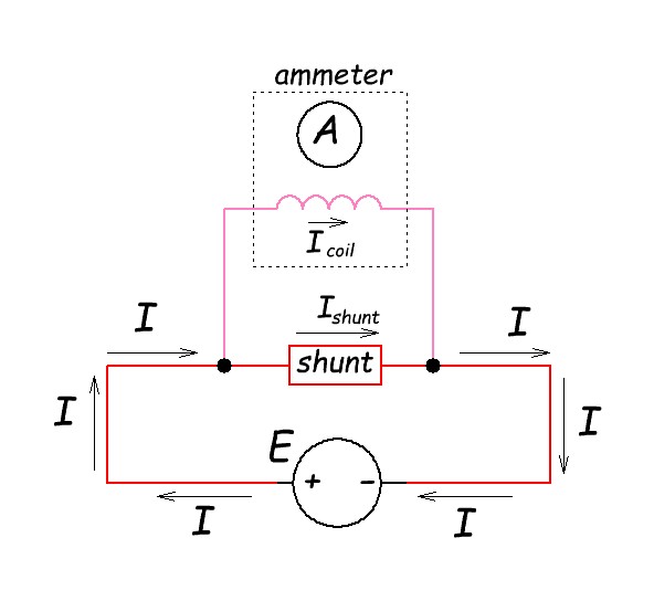
What is the shunt for? You and I know that a shunt is a low resistance resistor, therefore the main current will flow through the shunt. A negligible current will flow through the coil of the ammeter. With the shunt, we were able to increase the measurement range of the ammeter current.
To be honest, the ammeter scale shows the voltage drop across the shunt. It’s just that the ammeter dial is already calibrated in Amps. Why is that? The point is that the more current flows in the common circuit, the greater the voltage drop across the shunt. Ohm’s Law. I=U/R —> U=IR. You can read how to measure current with a shunt in this article.