
Ohm, a man who lived in the 18th-19th century, discovered the relationship between current, voltage, and resistance through experiments. This finding had a tremendous impact on electrical engineering, leading people to immortalize his name. As a tribute to him, it has been named Ohm’s law ever since.
- Hydraulic analogy
- Same pipe diameter
- Same water level
- Ohm’s law formula
- Ohm’s Law in practice
- Changing the voltage
- Changing resistance
- Ohm’s law for the complete chain
- Ideal voltage source
- Non ideal (practical) voltage source
- Ohm’s law for the complete chain formula
- How to measure the battery EMF
- How to find out battery internal resistance
- How to find EMF and internal resistance in practice
- About the internal resistance
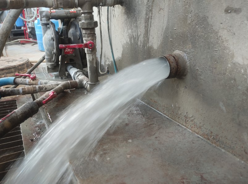
Hydraulic analogy
If you read the voltage article, remember this image.
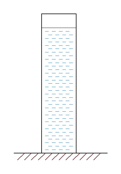
As you remember, the more water in the water tower, the more that water presses on the bottom of the tower.
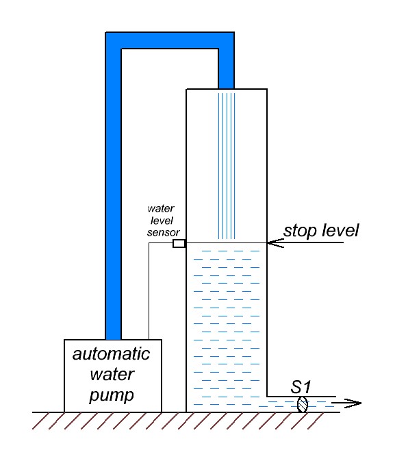
Let’s place a water pump next to the water tower that will pump water into our water tower. We will install a water level sensor on the water tower. When this level is reached, the water pump will be turned off. If the water level in the water tower is even a millimeter lower, the pump will immediately start again and pump water up to the “stop level”.
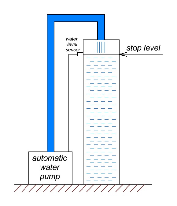
In such a system, we will always have a full full tower of water up to the stop level. You could say that there will always be constant pressure at the bottom of the tower.
Same pipe diameter
Let’s weld a pipe to the bottom of the tower.
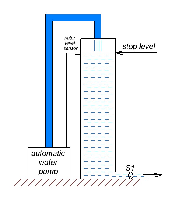
So no matter how much water flows out, we will always have the water level at the same ‘stop level’ as the water pump will pump the required amount of water.
So at the base of the water tower, we will have something resembling this.
Since we will always have the water level in the water tower at the stop level, we will always have the same volume of water flowing through the cross section of the pipe in 1 second. Doesn’t that wording remind you of anything? Of course it is! In the hydraulics analogy, that’s what the current is!
But what happens if we only fill the tower halfway?
Will the flow force from the welded pipe be reduced? I believe I am. So why will this happen? The fact is that the water level has halved, which means that the pressure on the bottom of the tower has also halved.
What about this?
Well, here the water flow is going to be very weak. Scientifically speaking, hydrostatic pressure is to blame.
Here’s a visualization of what we talked about above.

Each of the three holes has the same diameter. But the more water above the level, the stronger the jet.

If you consider each case in one picture, it would look like this:

If you don’t believe the picture, watch a video about hydrostatic pressure.
What conclusions can be drawn? In all three cases, the diameter of the pipe was the same. But the more water there was in the tower, the stronger was the water flow from the pipe. If we apply this to electronics, we can say that the higher the voltage, the higher the current for a constant resistance.
Same water level
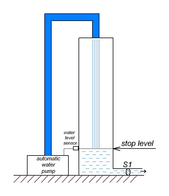
Let’s go back to our first picture.
Let’s weld a pipe to the bottom of the tower.
What happens if we increase the diameter of the pipe?
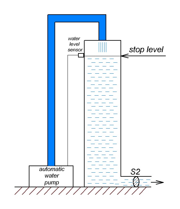
S2>S1.
In this case, more water will flow out of the pipe than in the first case in 1 second. In this case, we have increased the diameter of the pipe, thus the cross-sectional area of the pipe has become larger.
If you remember the formula from electronics, the resistance formula looks like this:

By increasing S (cross section area) , we decrease the resistance.
Let’s move on to electronics now. The water level is a voltage. It is always constant because the water pump is running. In this case, we only change the resistance of the pipe. But as you can understand, the larger the diameter of the pipe, the less resistance to water flow. So by decreasing the resistance we increase the current.
Ohm’s law formula
As you and I have found out, the strength of the current depends on the voltage and resistance. And the relationship is linear. Georg Ohm derived this law from simple experiments. The formula is very simple:
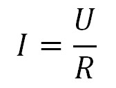
I – current, A
U – voltage, V
R – resistance, Ohm
Ohm’s Law in practice
In order to show Ohm’s law in practice, we will need a laboratory power supply and resistors of different ratings.
We will also, by analogy with the water tower, consider two cases:
1) changing the voltage on the power supply (water level in the water tower)
2) change the resistance (diameter of the pipe coming out of the base of the water tower)
Okay, let’s go.
In order to do this experiment, instead of a resistor, I will take a special device called an electronic load.
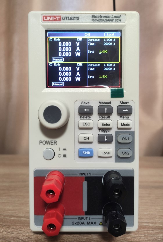
Changing the voltage
As I said before, in the first experiment we will always have a constant resistance. So, we need to set the electronic load in the constant resistance mode (CR mode). I set the resistance to 100 ohms right away.
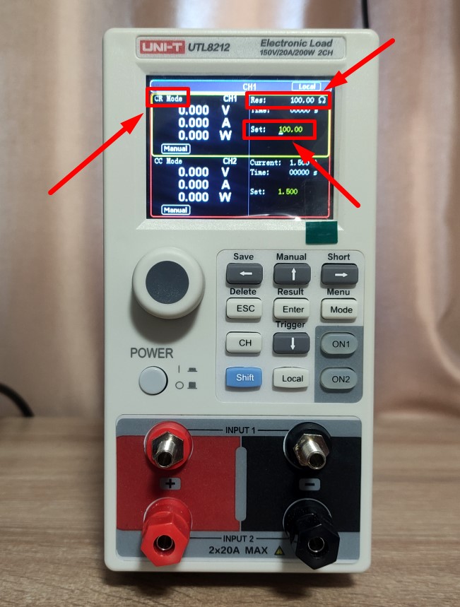
Well now it’s time to learn how Ohm’s Law works. From the lab power supply, I apply a constant voltage of 5 volts to the electronic load.
So, what do we have here?
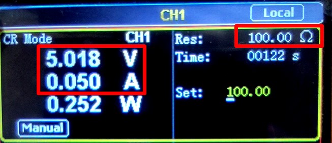
Voltage 5 V
Resistance 100 Ohm
Current 0,05 A
0,05=5/100 right? The formula works!
Let’s increase the voltage to 10 volts
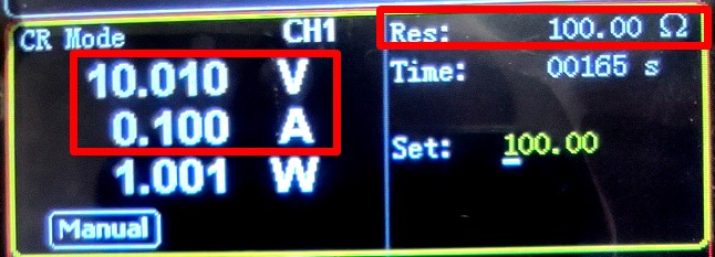
0,1 = 10/100. Perfect!
Maybe it’s just a coincidence. Let’s add a little more voltage.
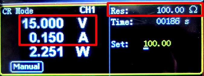
0,15=15/100.
As you can see, Ohm’s law works perfectly!
Changing resistance
In this experience, we will always have voltage at a constant value. If we consider the analogy of a water tower, there will always be the same water level in the tower, no matter what diameter pipe is welded near the base of the tower. We will change the resistance and the voltage will be constant.
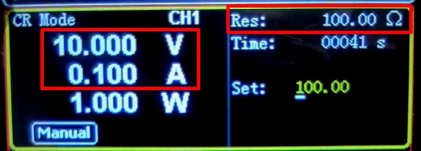
0,1=10/100
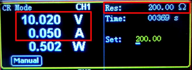
0,05=10/200
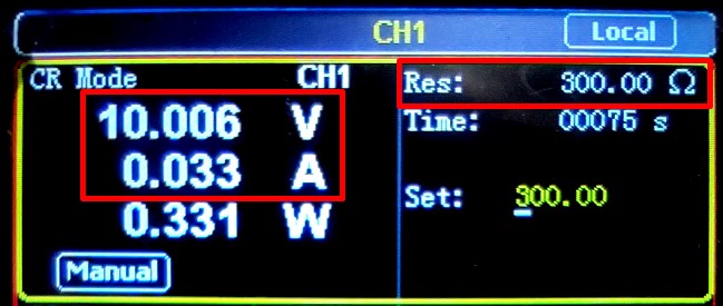
0,033=10/300
That’s wonderful! The formula works correctly.
Ohm’s law for the complete chain
In the Ohm’s Law, we discussed the relationship between voltage, current, and resistance. But there is also another lesser known Ohm’s law: Ohm’s law for the complete chain.
Ideal voltage source
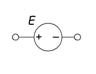
What is an ideal voltage source? It is a voltage source that always outputs a constant voltage value, regardless of the load at its terminals. One more important note: an ideal voltage source is the EMF. The EMF source is labeled with the letter “E”.
We can connect an infinite number of loads to such a voltage source and its voltage will not change in any way.
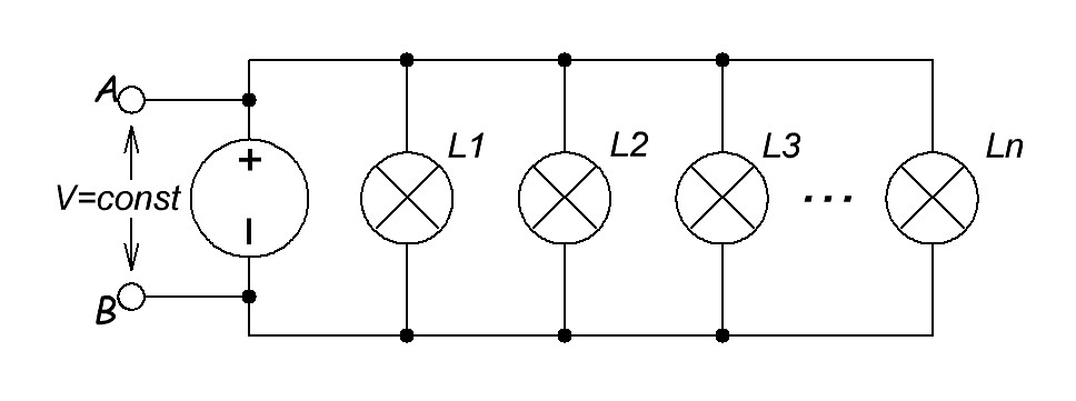
If it’s simpler to draw
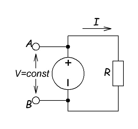
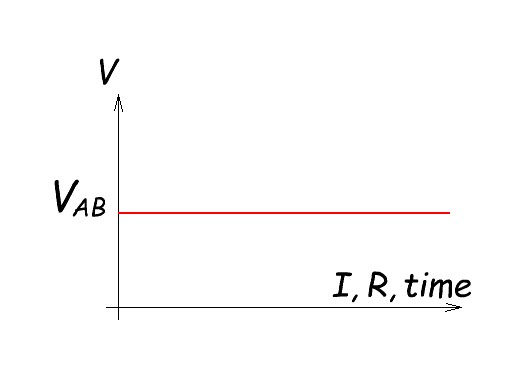
The graph of such an ideal voltage source will look like this:
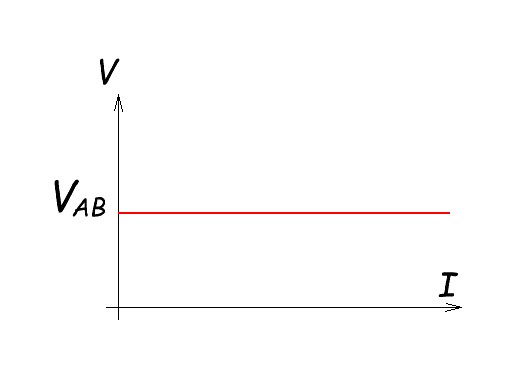
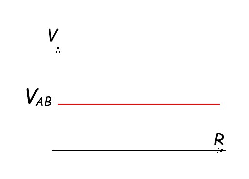
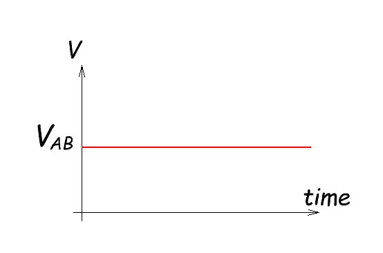
If we combine all these graphs into one graph for convenience:
But you know what the catch is? The ideal voltage source does not exist in real life!
Non ideal (practical) voltage source
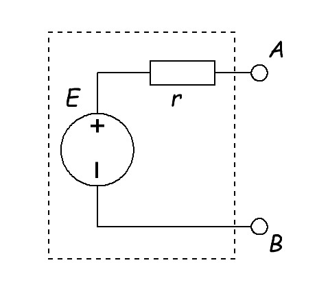
As you know, nothing is perfect in our world. Otherwise everyone would be rich, beautiful and happy. It’s the same in electronics. There is only a non ideal voltage source. It’s also called a practical voltage source. What is the difference from the ideal? It’s pretty simple. A practical voltage source has an internal resistance (r) in it .
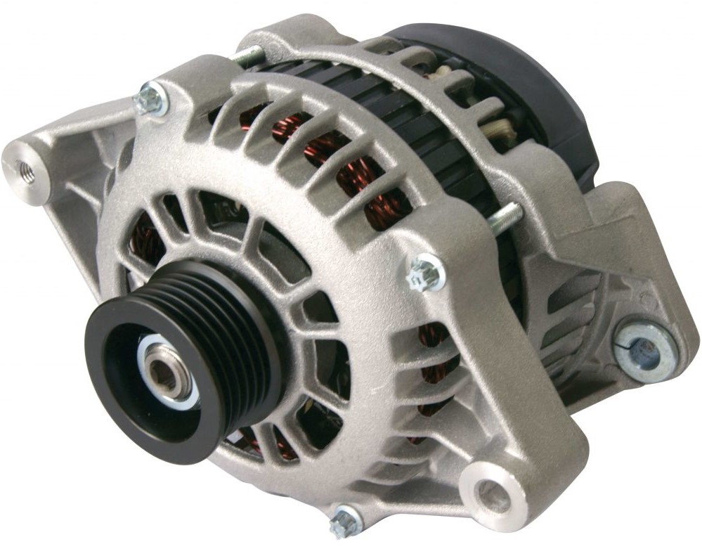
The practical voltage source is all chemical voltage sources and various generators of electric current.


The wiring diagram of a car battery will look like this:
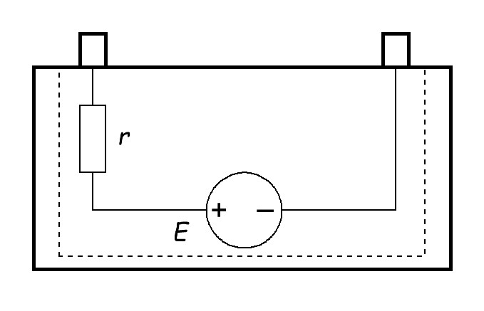
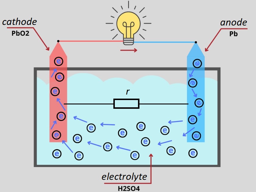
Where does this internal resistance in chemical current sources even come from? This is the resistance of the electrolyte, plates and terminals of the battery itself.
For example, in an car generator, it is the resistance of its working wound windings.
So we can say that any source of electric current has this internal resistance. And this internal resistance always goes in series with the EMF source.
Ohm’s law for the complete chain formula
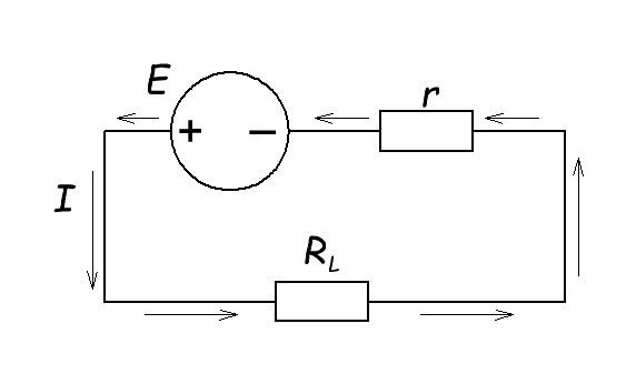
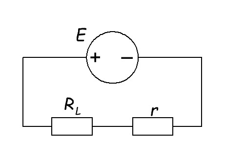
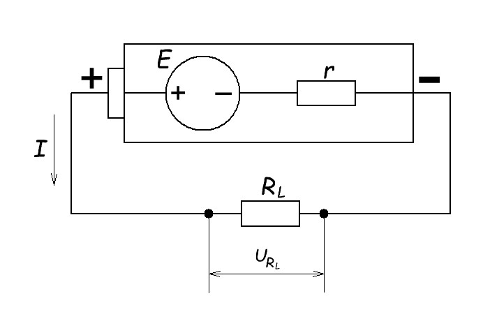
If we look at a simple cylindrical battery or accumulator, their electrical circuit will look like this:
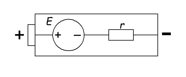
One quick note: internal resistance (r) is not a resistor that is connected before or after an EMF source. As I said, it is the total resistance of the substance that makes up the EMF generator. It doesn’t matter it is before or after the EMF source (E), the important thing to remember is that it is connected in series.
For ease of perception, let’s remove all unnecessary things. So, in a simple way, we get an EMF source and a resistance that is connected in series.
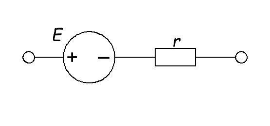
Let’s connect the load (RL).
Our electrical circuit will become closed and an electric current will run through it.
Remember Ohm’s Law:
We have the load resistance (RL) and the internal resistance (r) connected in series, then the total resistance can be expressed as:
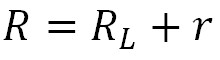
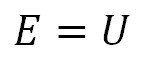
Since the ideal EMF source we have always produces a constant voltage, this is the voltage used in Ohm’s law.
Therefore, formula Ohm’s law for the complete circuit will look like this:
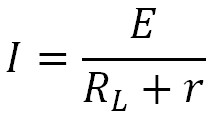
I – current, Amps
E – EMF, Volts
RL – load, Ohms
r – internal resistance, Ohms
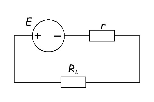
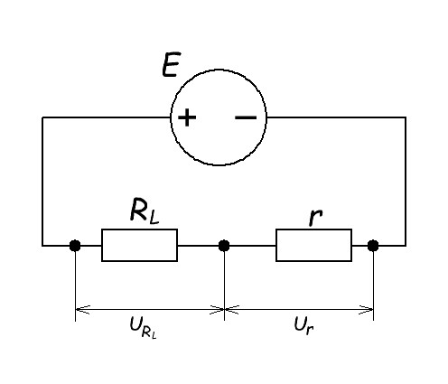
Let’s redraw the diagram for convenience.
Wow! Now we can clearly see that these resistors are connected in series.
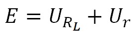
As you know, if resistors are connected in series, they form a voltage divider. This means that the sum of the voltage drops on each resistor equals the EMF of the circuit.
If the resistors are connected in series, the same current will flow through them.
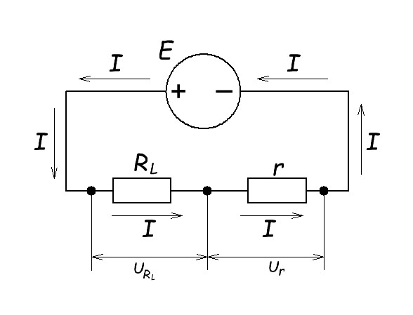
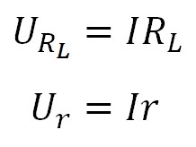
From the simple Ohm’s law we can write:
What conclusions can be drawn from here? The greater the current in the circuit, the greater the voltage drop across each resistor. Since the internal resistance (r) varies only slightly, the current in the circuit depends mainly on the load (RL).
How to measure the battery EMF
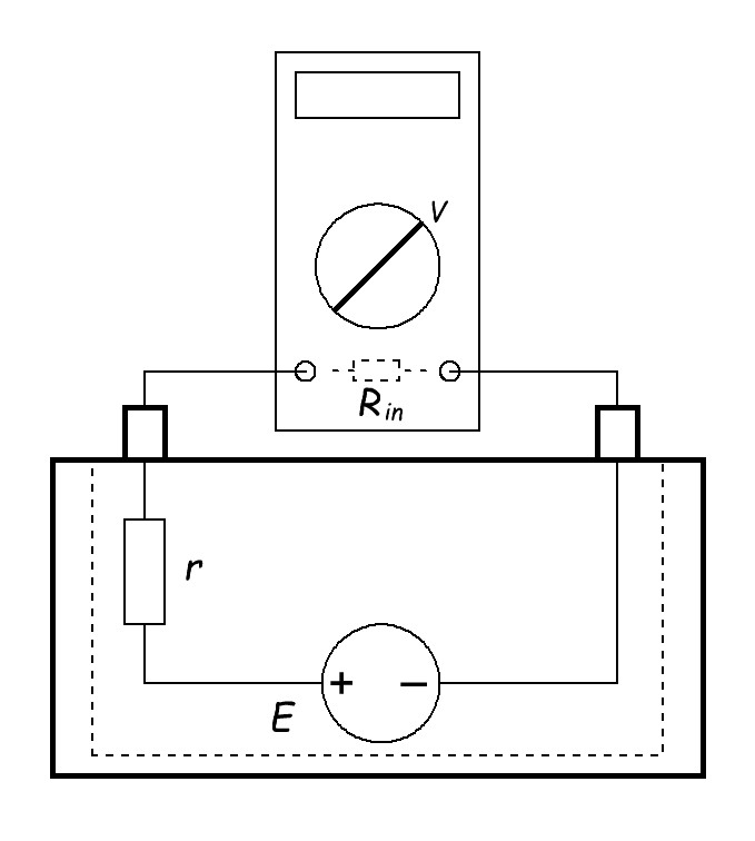
Let’s take another look at our battery or car battery.
If we measure the voltage on the battery with a multimeter, it is the EMF that we will see on the multimeter display. Why is that? Simply put, there is a very large resistance between the multimeter probes that does not affect the circuit in any way. In electronic terms, the input resistance (Rin) of the multimeter in the voltage measurement mode is very large.
In Chinese cheap multimeters it is from 1 megaohm. More expensive and better quality multimeters have an input resistance of 10 megohms or more. Therefore, when measuring voltage, the current in the circuit will be very small. This means that a negligibly small current will flow through the internal resistance. So, the voltage drop across the internal resistance will be zero. From the above, the multimeter will display the battery EMF voltage (E). That’s how easy it is to measure the battery EMF voltage.
Summarise: to find out the EMF of a battery, simply measure its voltage with a multimeter.
How to find out battery internal resistance
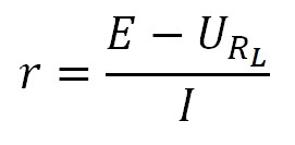
Let’s find the internal resistance through the EMF formula.
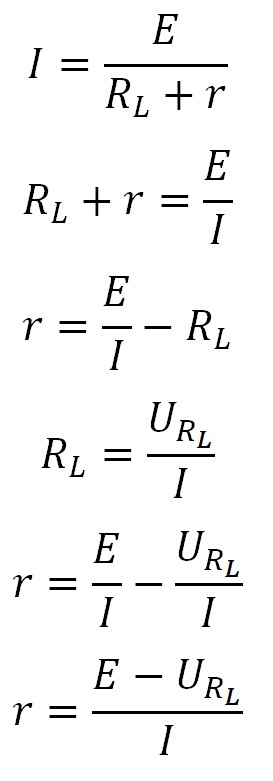
By this simple formula we can find the internal resistance of any chemical current source or EMF generator.
How to find EMF and internal resistance in practice
We have a lithium-ion battery 21700.
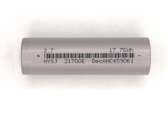
So, by measuring the voltage on a battery we get the value of EMF (E). If you don’t know how to do it correctly, you can read here.
How do we find the internal resistance of our battery? We’ll use this formula:
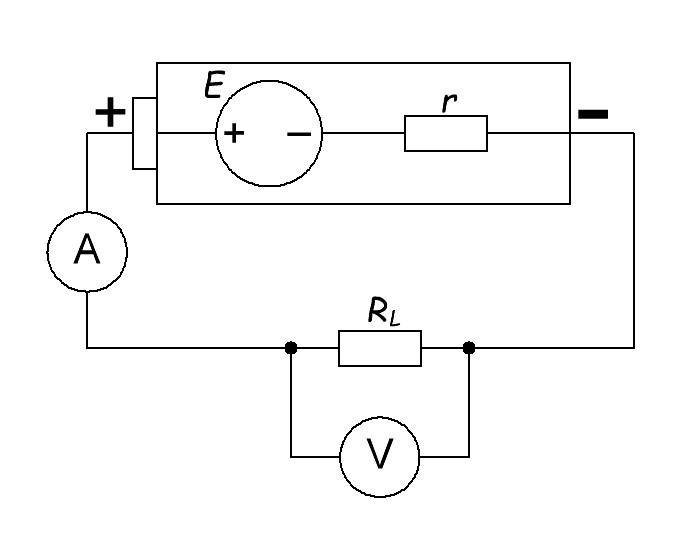
and this diagram:
So how do we measure the current (I) and voltage drop across the load resistor (URL)? The answer is obvious. With an ammeter we will measure the current and with a voltmeter we will measure the voltage.
A complete circuit for measuring internal resistance would look like this:
As a load resistance (RL) I will use again a special device called an electronic load
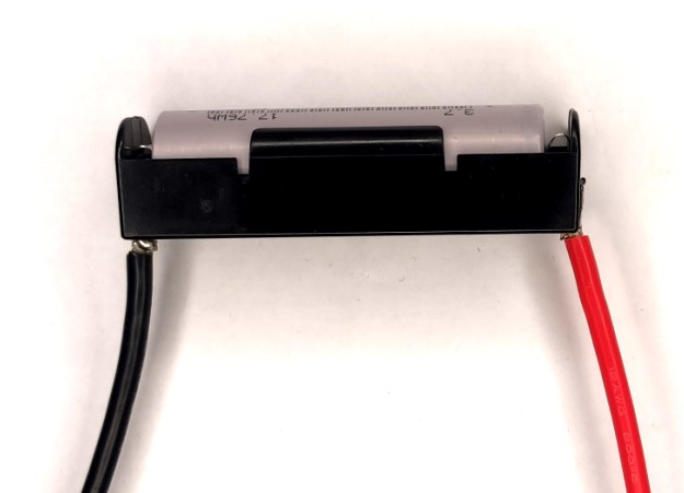
and a case for 21700 battery with 12awg wires (3.4mm2 cross-sectional area). The thicker the cross-section of the measuring leads, the better.
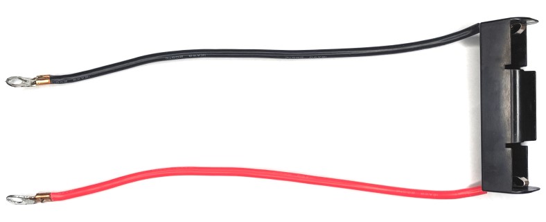
Why? Well, we’re going to measure the internal resistance of the battery, not the wires. The thinner the wire, the greater the resistance. We talked about this in the article resistance.
Insert our battery into this case.
Connect the wires to the electronic load.
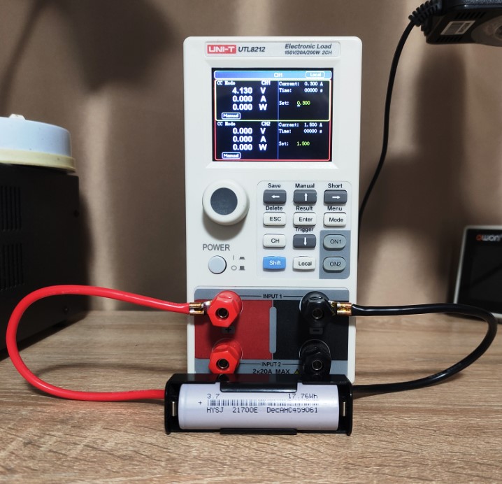
Immediately, what you can see on the display of the electronic load is the battery voltage.
We will see almost the same value if we measure the voltage with a multimeter.
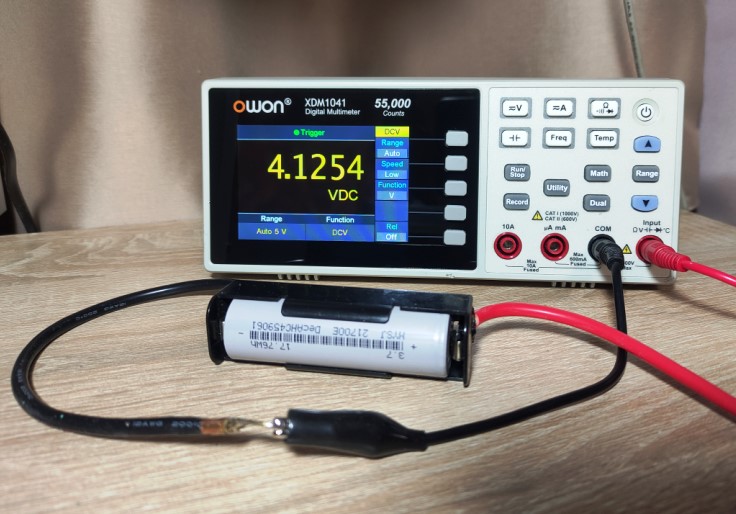
Now we measured the battery’s EMF (E). E=4.13 Volts.
My electronic load can show both current and voltage at once. All I have to do is pick a load resistor so that the current in the circuit is about 1-1.5 Amps. 3 ohms will be enough. When selecting the resistor, do not forget that it will generate power in the form of heat according to the formula P=IU. You can read more about this effect in this article.
I set the value to 3 ohms and press the ON1 button on my measuring device.
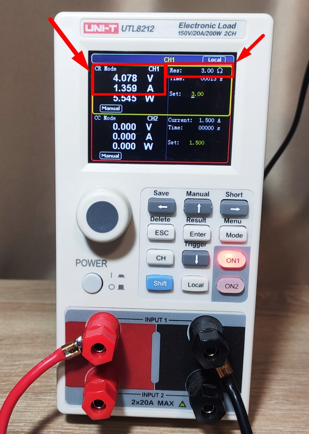
So, E=4.13 Volts, URL=4.078 Volts, I=1.359 Amps. Insert these values into the formula:
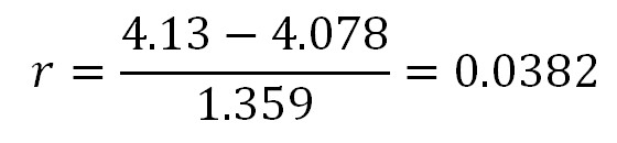
The internal resistance of our battery 38 mOhm.
About the internal resistance
Internal resistance is not a constant value unlike a resistor. As a battery ages, its internal resistance increases. The internal resistance also depends on the temperature. At minus temperature, the internal resistance of the battery increases many times. The lower the temperature, the higher the internal resistance. During exploitation, the voltage on a battery drops and the internal resistance increases.


I’ve been browsing online more than three hours today,
yet I never discovered any interesting article like yours.
It is pretty value sufficient for me. Personally, if all website owners and bloggers made just right content material as
you did, the web shall be a lot more useful than ever before.
Thank you for your feedback! I will try to write even better and more interesting articles)