Resistor is a radioelectronic component that has two outputs and provides resistance to electrical current. That’s the official terminology. But in fact, the resistor is a very important and the most common radio element in electronics, and it does much more than just electrical current resistance. Let’s talk about this more.
A resistor is the most common radio element used in electronics. You will find at least one resistor on any device electronics board. A resistor has an important property – it has an active resistance to electric current. And of course, the most important property of a resistor is its resistance. The word resistor comes from the word resistance.
- What a resistor is for
- Resistance of a resistor
- How to measure the resistance of a resistor with a multimeter
- Power dissipation on the resistor
- Resistor types
- Resistor with fixed value (fixed resistors)
- Carbon film resistors
- Metal film resistors
- Wirewound resistors
- SMD (chip) resistors
- Variable Resistors
- How a variable resistors work?
- How to know the resistance of a resistor without multimeter
What a resistor is for
The resistor is needed to limit the current. How does it work? Let’s look at the operation of a resistor by analogy with hydraulics.
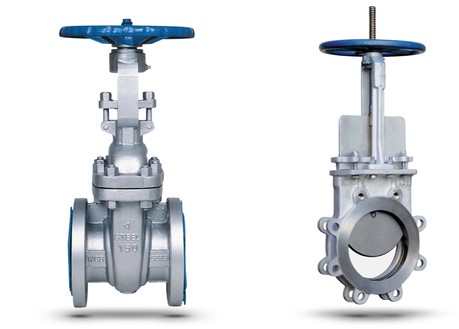
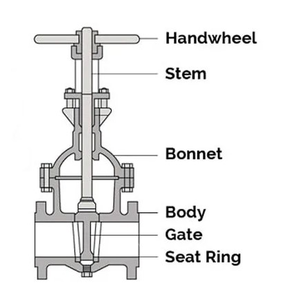
Do you know what a gate valve is and how it works? Turn the handwheel and adjust the gate position.
Let the water flow through the pipes
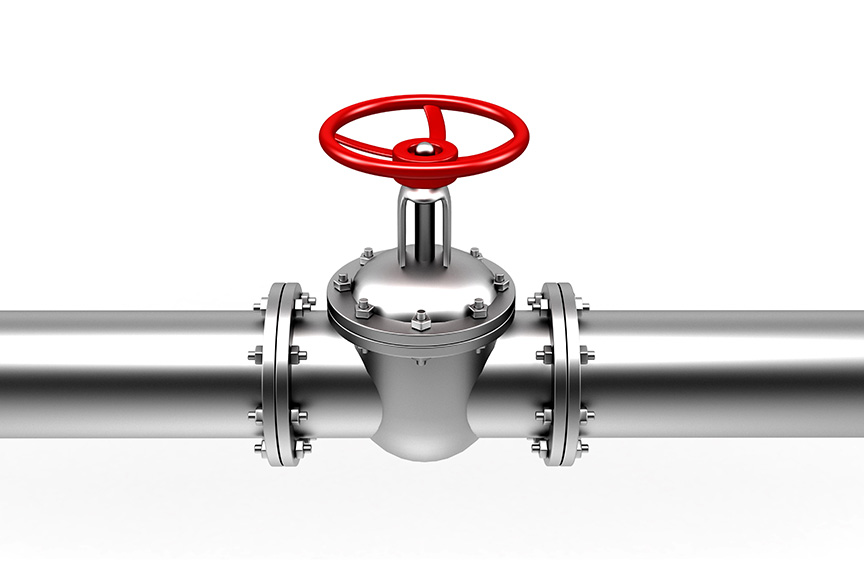
Let’s take a look at the picture below.
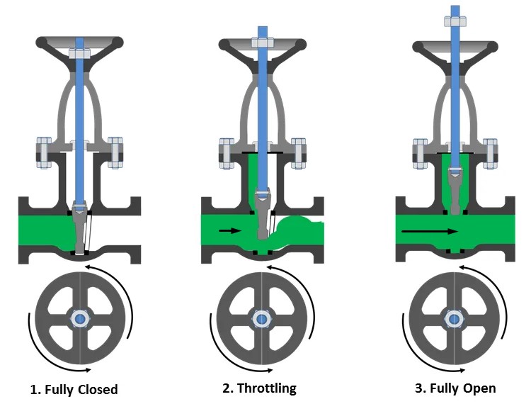
So we have three gate positions.
- Fully closed
- Throttling
- Fully open
In the first case, although water is pressurized, it cannot flow through the pipe because the gate is completely closed. In the electronics analogy, we have voltage but no current. Notice that the water is pressing on the gate.
In the second case, we opened the gate quite a bit and the water started running slowly.
In the third case, we opened the gate completely and the water started to flow very fast because there are no obstacles in its way.
Let’s look at the second case in more detail.
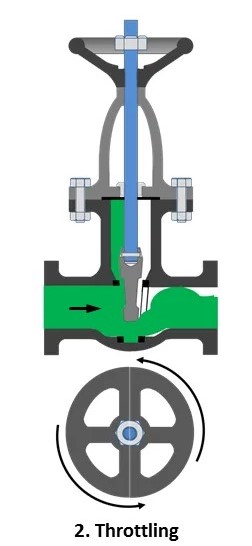
As you can see, the gate prevents water from flowing through the pipe. The more we raise the gate, the stronger the water flow will be. There is also a simple rule of thumb: the rate of water flow before the gate is the same as after the gate.
A resistor does the same thing in electronics. It limits the flow of electrons through the wire. So you could say it can regulate the current.
Resistance of a resistor
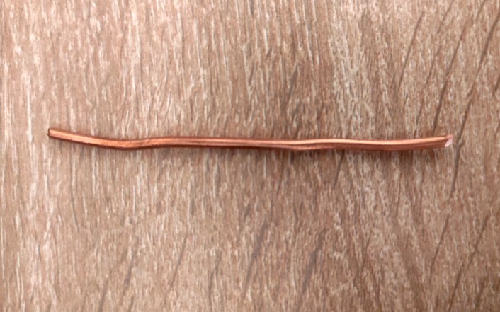
So, what does the simplest resistor look like? You won’t believe this, but it’s the simplest metal wire. It can be made from any metal. Here, for example, is a piece of copper wire. This could be considered a resistor.
What factors influence the resistance of a substance? We talked about all of this back in the resistance article. I can remind you of some of the points in this article.

R – resistance, represented by the capital Greek letter omega (Ω) or “ohm”.
l – length of wire, m
ρ – resistivity, Ω⋅m
S – cross section area, m2
So, the resistance of a resistor will depend on the substance from which it is made, the cross-sectional area of that substance, and the length of that substance.
Absolutely any metal conductor can be a resistor. Generally, all substances have some kind of resistance, but not all of them are used in electronics.
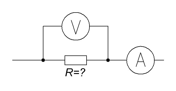
How to measure the resistance of a resistor with a multimeter
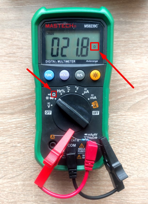
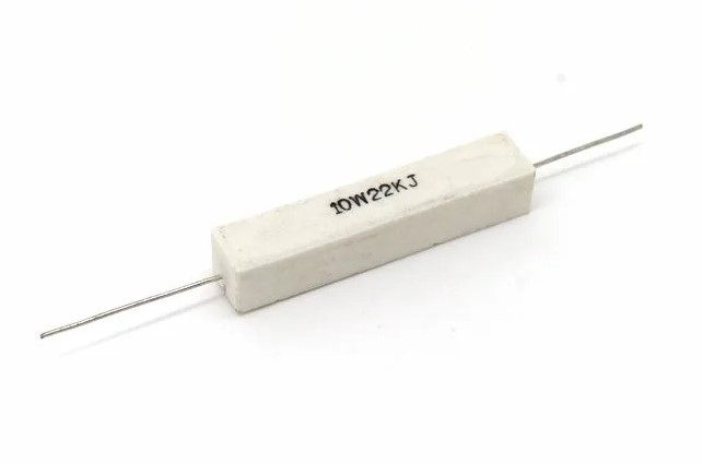
In order to measure resistance, we need to find this icon (Ω) on the multimeter. Place a switch on this icon and connect the probes to the resistor leads. In my case, a 22 ohm resistor.
Power dissipation on the resistor
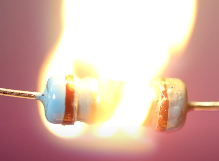
Each resistor dissipates electrical power into the surrounding space. Each resistor is designed for some maximum power dissipation. If this power is exceeded, the resistor will literally burn up.
There are simple formulas for calculating the power dissipation on a resistor.
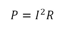
P – power dissipated on the resistor (watts)
I – current flowing through the resistor (A)
R – resistance of the resistor (ohm)
If you don’t know what current is flowing through the resistor, you can calculate the power dissipation through the voltage that drops on the resistor.
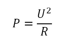
P – power dissipated on the resistor (watts)
R – resistance of the resistor (ohm)
U – voltage drop on the resistor
If you don’t know the resistance of the resistor at all, you can use a simple formula.
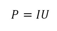
P – electric power, W (watt)
I – current, A (amps)
U – voltage , V (volts)
We need to see what voltage drops across the resistor and what current goes through the resistor. And then multiply these values.
Resistor types
Nowadays, resistors are made small and compact for low-current electrical circuits and large and powerful for power circuits of electric current.
Let’s take a look at some of the most popular types of resistors.
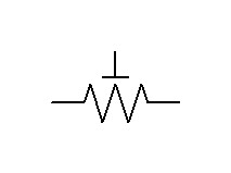
Resistor with fixed value (fixed resistors)
In wiring diagrams, permanent resistors are marked with this icon:
Let’s take a look at the main types resistors with fixed value
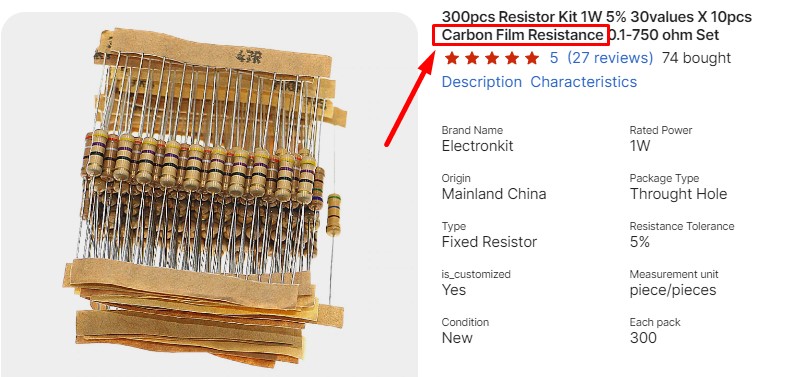
Carbon film resistors
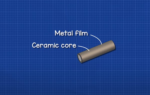
These are the most common and cheapest types of fixed resistors. Their construction is very simple.
They are made of ceramic core

coated with a thin carbon film

and metal connectors on each side

and the whole structure is then covered with insulation

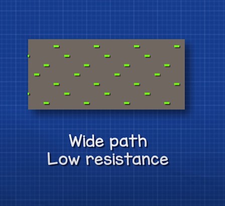
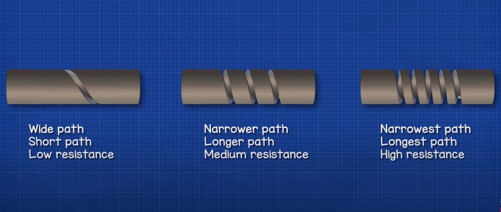
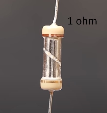
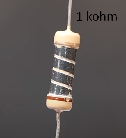
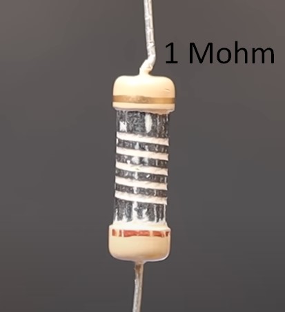
To control the resistance value a helical groove is then cut into the layer of carbon.
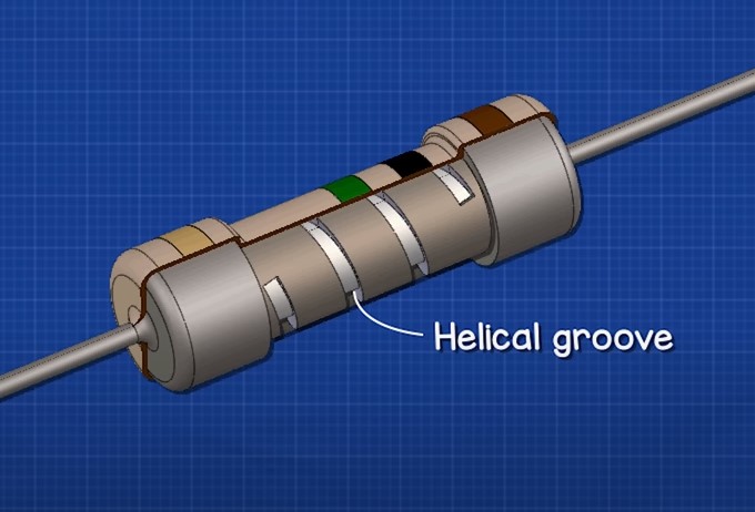
What are the grooves for? With the help of the cut-out grooves, the resistance value can be adjusted over a very wide range.
Let’s look at the resistance formula again.
This formula is used when making resistors of different ratings.

Let’s remove the insulation and see what resistors with different resistances look like.
Metal film resistors
If the ceramic core is covered with a thin layer of metal, we get metal film resistor.

The required resistance value is also achieved using cut grooves in the metal film of the resistor.


What’s the difference between carbon and metal film resistors? Metal film resistors have high tolerance and they a little bit expensive than carbon film resistors.
How can I visually identify carbon film and metal film resistors? Carbon film resistors have a yellow colour and metal film resistors have a blue colour.

And as I wrote before, metal film resistors have a good tolerance compared to carbon film resistors. Carbon film resistors have about 5% deviation from rating. This means that if we take such a resistor and measure its resistance, we will see that its resistance can differ by 5% up or down. For metal-film resistors, this deviation is less than 1%.
We have one carbon film resistor and one metal film resistor. They are rated at 1 kohm.
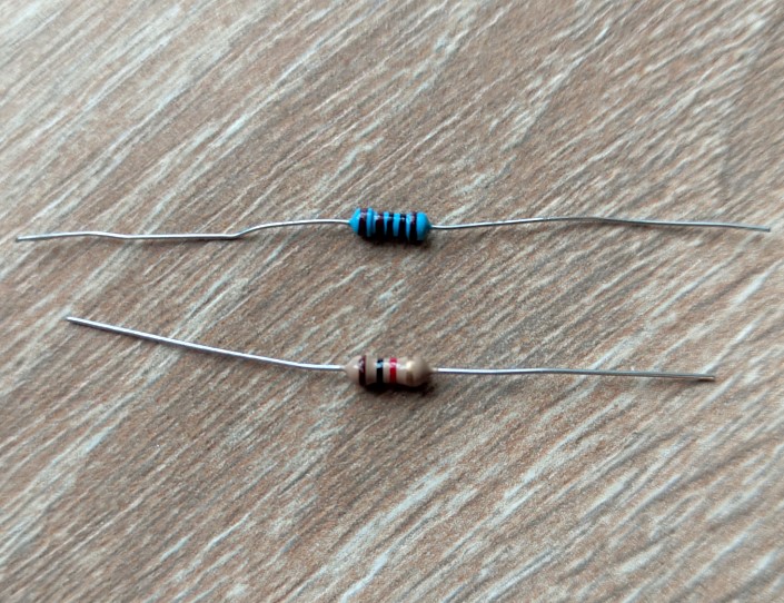
Let’s measure their resistance.
Metal film resistor
Carbon film resistor
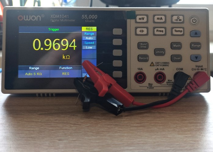
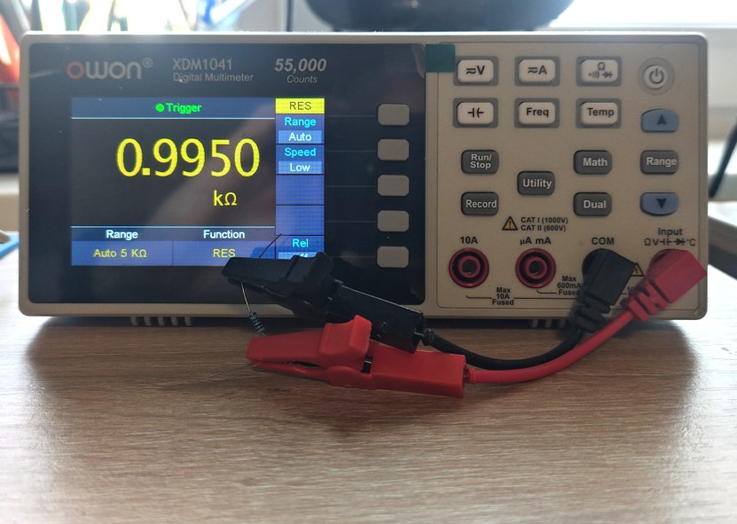
Can you feel the difference? For a 1 kohm metal-film resistor, a 1% deviation is 990…1010 ohms. We can see 995 ohm. It’s normal. For carbon film resistor 5% deviation is 950…1050 ohm. We measured 969 ohm. it’s OK. But as you could see, the metal-film resistor gives a more accurate value to the rating 1kohm. That is why I always advise you to use only metal-film resistors in your practice. Yes, they are a little bit more expensive, but their resistance is very close to the nominal value.
Carbon films and metal film resistors are available in different sizes.

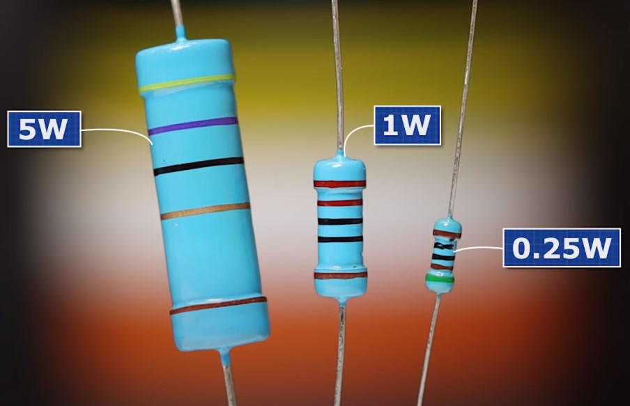
As you can see, the larger the resistor, the more power it can dissipate on itself.
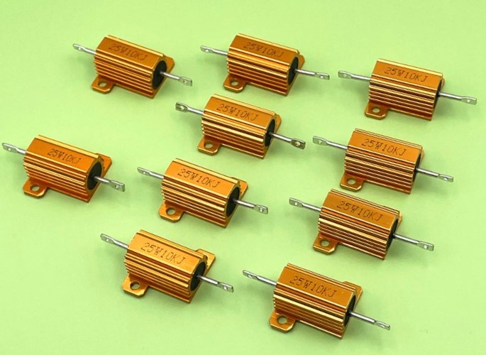
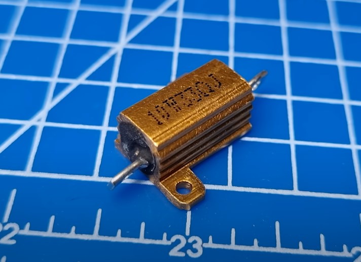
Wirewound resistors
Wirewound resistors look like this:
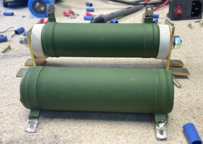

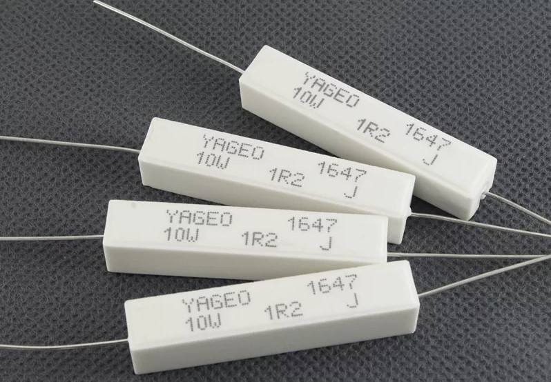
Why do they have a name like that? It’s all about the fact that they are made of wire or metal tape wound on a ceramic core.
With and without insulation:
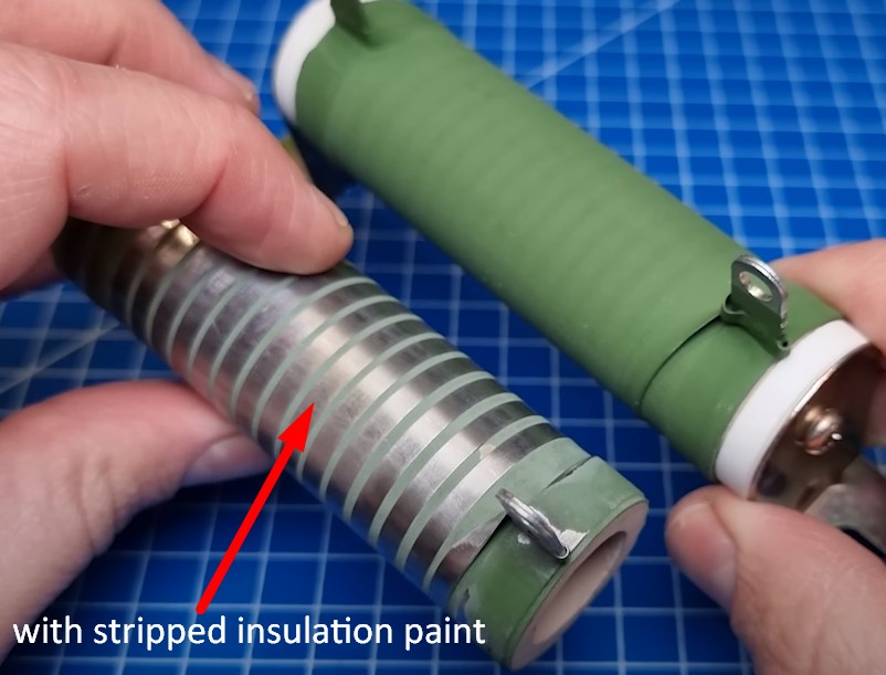
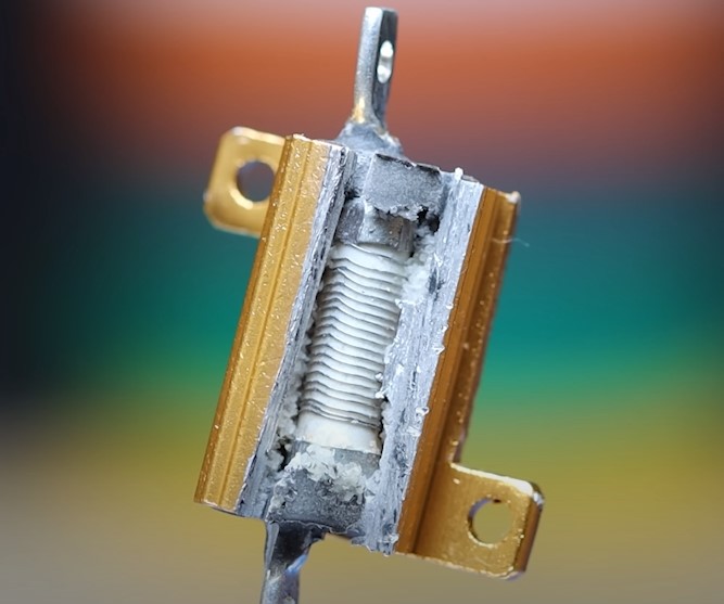
What inside this resistor?
We take a hammer and hit it.
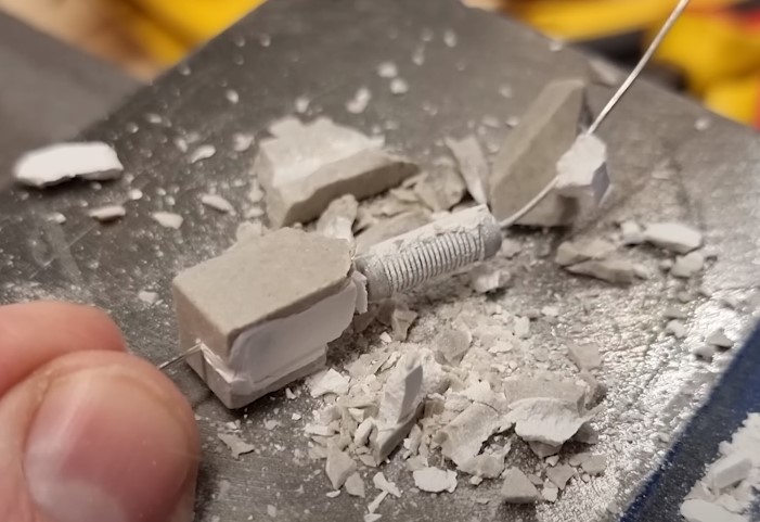
As you can see just a coil of resistive nichrome wire wrapped around a ceramic core.
We see the same thing here
Why are these resistors large and even with a heatsink? They are used in industrial electronics in manufacturing and a large amount of current flows through these resistors. It makes them start to heat up a lot. Therefore, they have a large dissipation power.
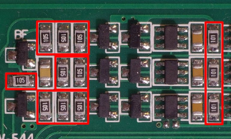
SMD (chip) resistors
SMD – Surface Mounted Devices. So SMD resistors are surface mount resistors. They are also called chip resistors.
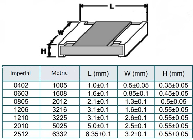
Basic Dimensions of SMD Resistors:
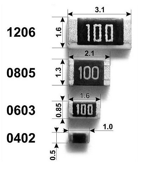
How can I know what size SMD resistor belongs to? It’s very easy. The first two digits indicate the length in 1/100 inches and the last two digits indicate the width in 1/100 inches. For example the SMD resistor 1206.
12/100 = 0.12 inches
06/100 = 0.06 inches
1 inch = 25.4 mm
So length of 1206 resistor = 0.12 x 25.4 = 3 mm
and width = 0.06 x 25.4 = 1.5 mm
Here is a table of SMD resistor sizes. Inch belongs imperial units.
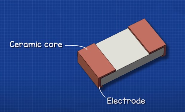
The construction of SMD resistors quite simple. They have a ceramic body with on an electrode on each end.
Electrodes are connected by a thin layer of resistive material
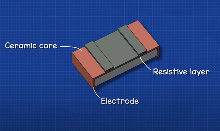
The metal leads are connected on the sides and covered with insulation on top.
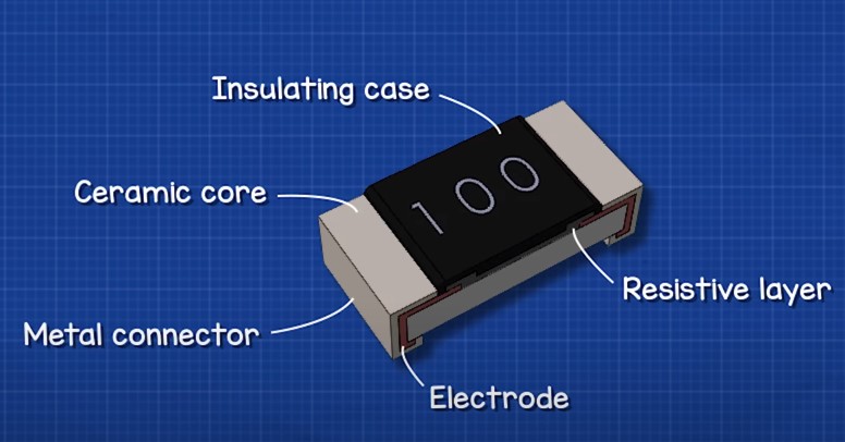
The resistive material has a groove cut into it with a laser.
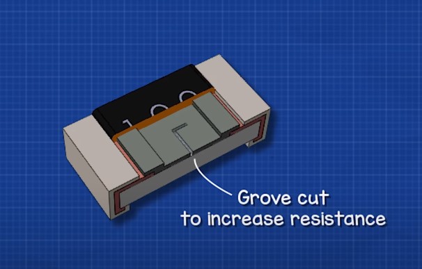
What is the purpose of this? In order to find the required resistance for the resistor.

Such resistors have very small power dissipation.
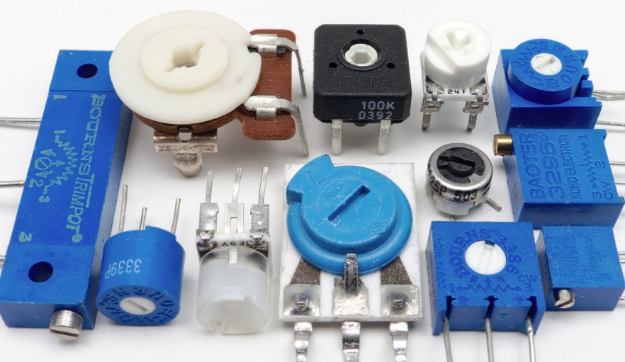
Variable Resistors
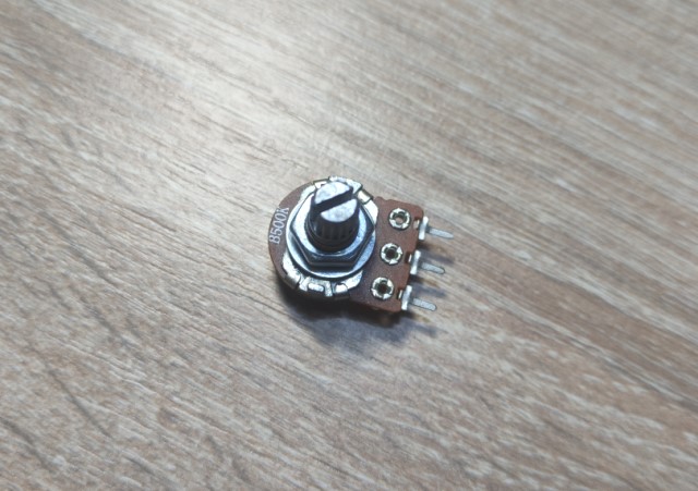
They look something like this:
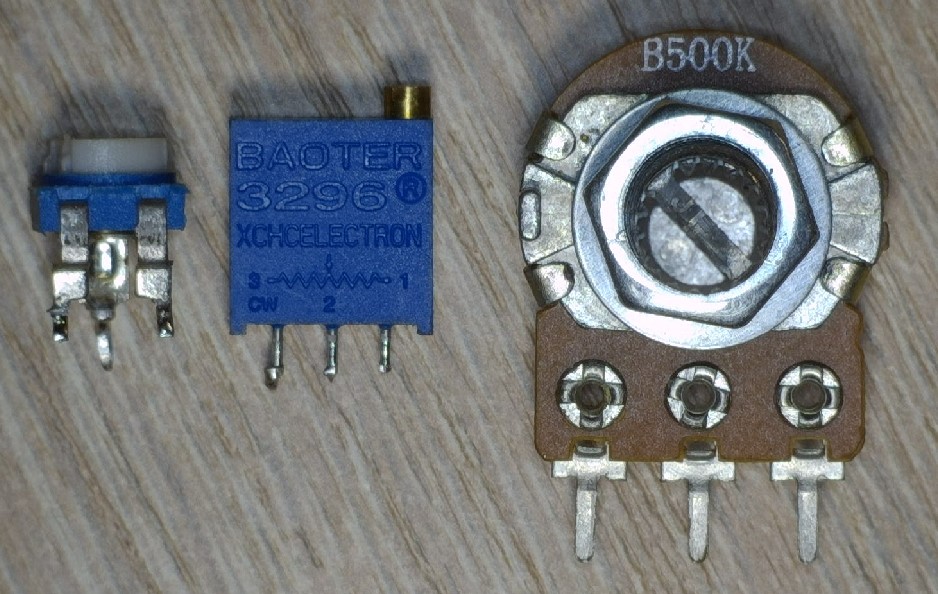
As you may have noticed, they have three outputs and a groove for resistance adjustment.
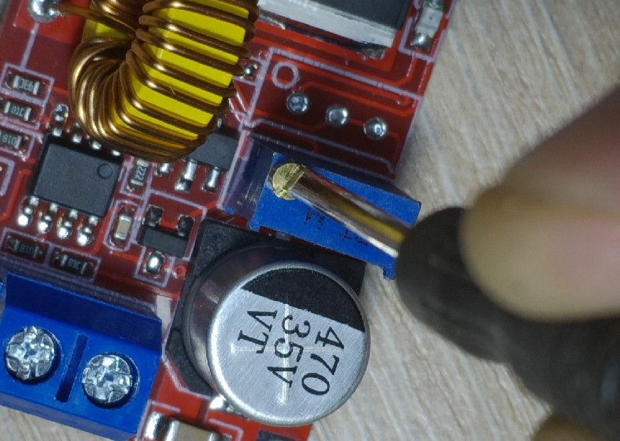
You can change the resistance of the resistor with a small screwdriver or just by hand.
So how are variable resistors identified on the schematic?
If we mean a variable resistor like this
In the wiring diagram it look like this
or
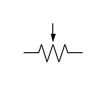
As you can see in the photo and in the wiring diagram it has three pins.

Variable resistors of this type are called preset resistors
The wiring diagrams are labeled like this
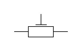
or
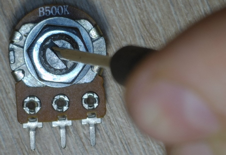
What’s the difference? If we need to change the resistance frequently, we would use a variable resistor like this.
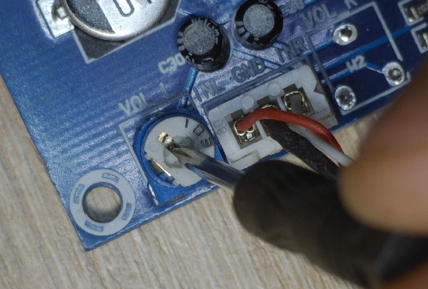
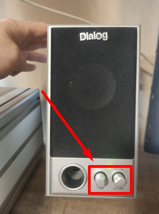
You may not realize they exist, but all of you have definitely changed its resistance. For example, they are used in an audio system to increase or decrease the volume and tone of music.
If we need to set a certain resistance and forget about it, then we need to use preset resistors.
How a variable resistors work?
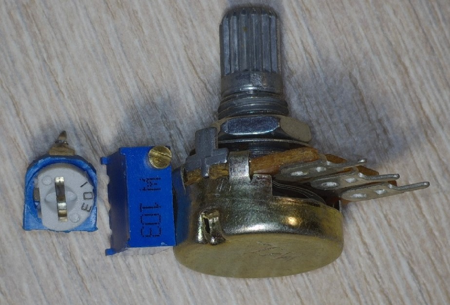
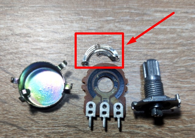
Let’s break down one variable resistor and see what it’s made of.
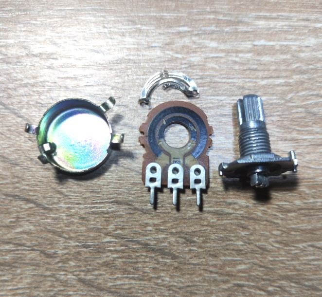
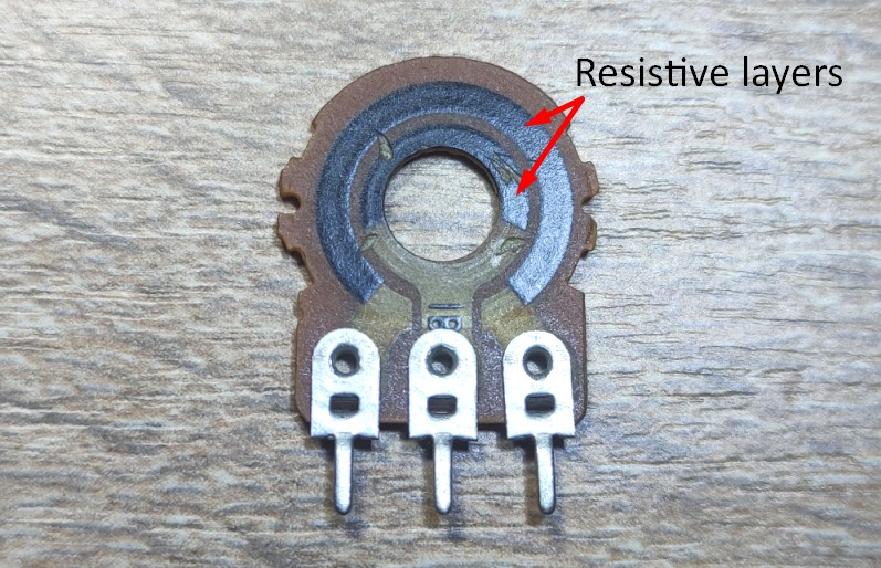
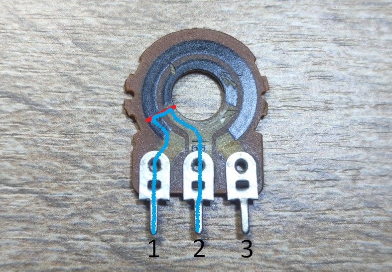
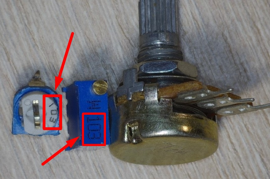
Sorry, I scratched the resistive layer a bit. As you can see, a variable resistor consists of two rings of resistive layer. The outer ring is incomplete and is interrupted by the two output pins of the variable resistor.
Let’s label the outputs of the resistor

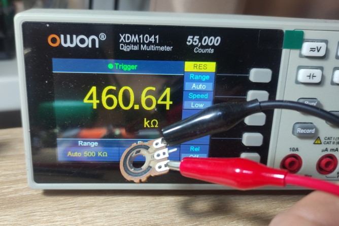
The resistance between pins 1 and 3 is always constant and depends on the resistive layer. The value of this resistance is indicated on the body of the resistor itself. In our case, it’s 500 kilohms.
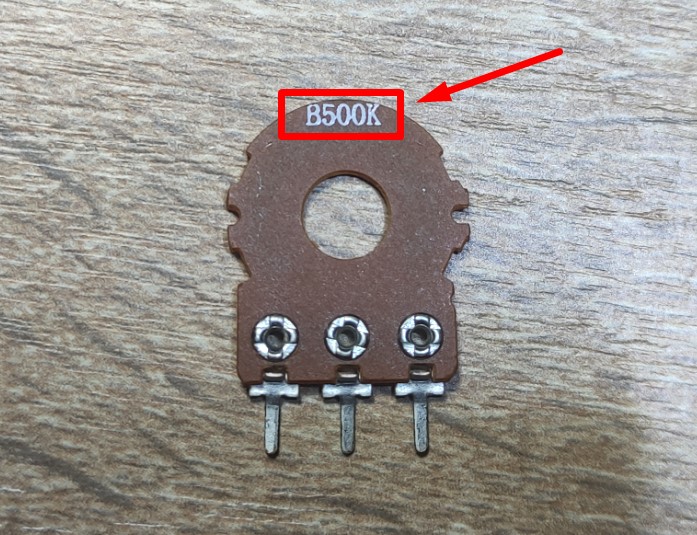
Let’s see if that’s true. 460 kohms. Well, what do you want with a Chinese resistor? )
Look at this detail. It connects the two circles of the resistive layer. It connects two points of some sort on the outer and inner circle.
So, the resistance between pins 1 and 2, 2 and 3 depends on where we connect our circles.
The formula for such a variable resistor is very simple.
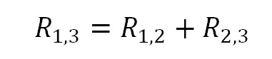
The resistance between pins 1 and 3 of the variable resistor is equal to the sum of the resistances between pins 1 and 2 , 2 and 3.
With the red line we will connect the two circles at this point.
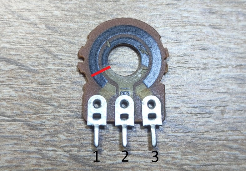
So on this section we have electric current running this way between 1 and 2. A small section of the resistive layer is encountered along our path.
Let’s take a look at this picture
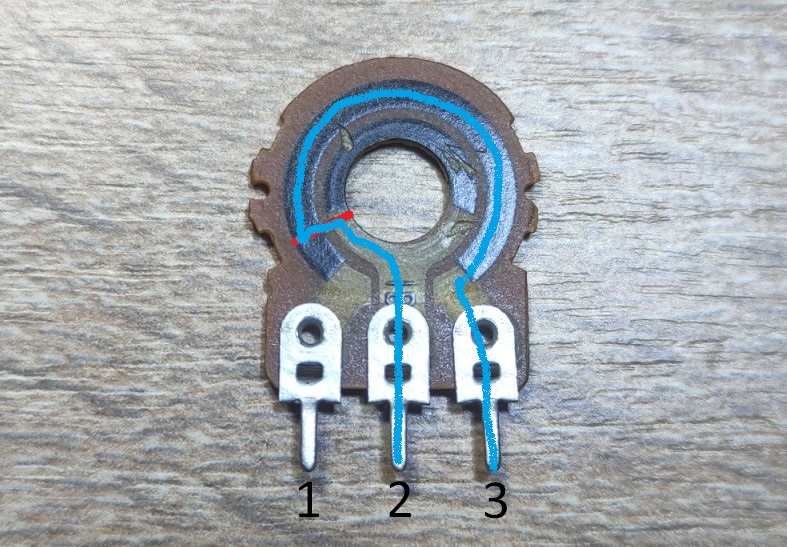
Such a long way for an electric current to travel through a resistive layer!
Where will the resistance value be greater?
Recall the formula
So ρ and S constant. l – length of wire is volatile. Based on the formula, the greater the length, the greater the resistance. Therefore, the resistance between pins 1 and 2 will be less than the resistance between pins 2 and 3.
How to know the resistance of a resistor without multimeter
The color rings are used to mark film and metal film resistors.
In order not to stress too much, smart people made an online calculator a long time ago.
Let’s see how this works with a real example.
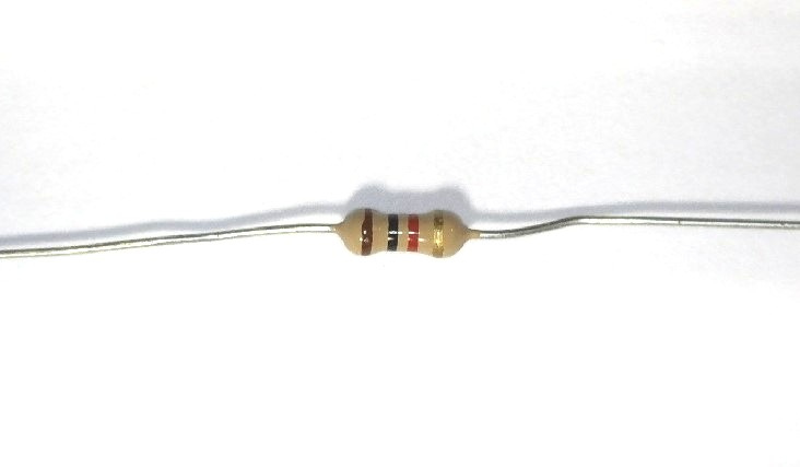
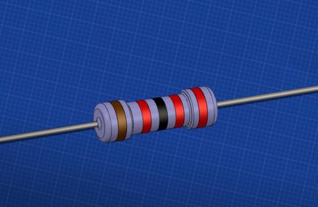
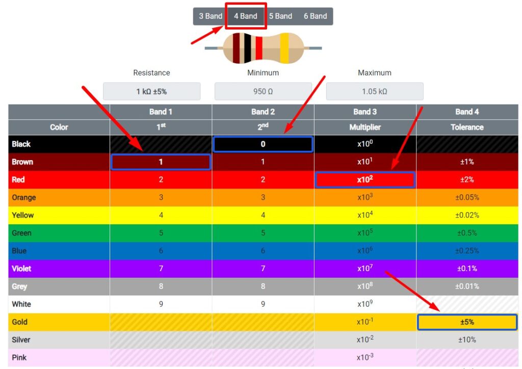
Our resistor has 4 bands. Colors: brown, black, red, gold.
Open resistor color code calculator and find out resistor rating.
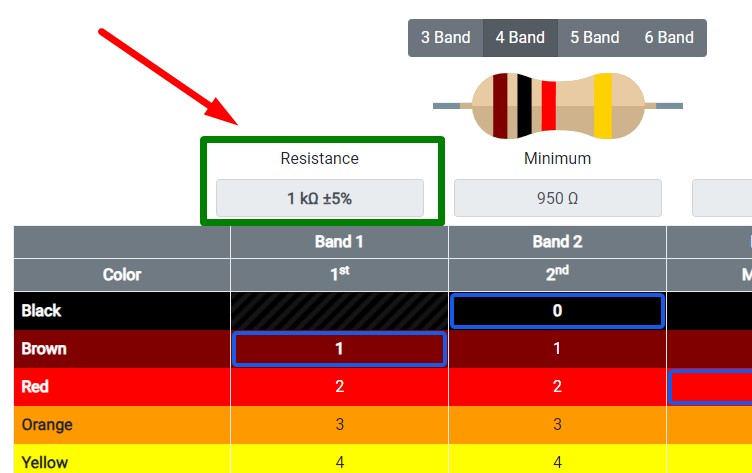
Let’s check the resistance of this resistor with a multimeter.
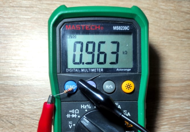
What about chip resistors? Let’s start with this chip resistor.

To measure the resistance of the chip resistor I will use this multimeter, which is used for easy measurement of SMD components.
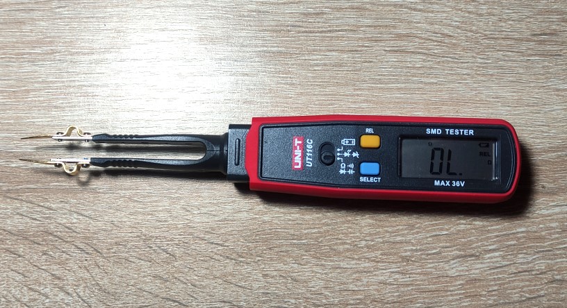
4,7 ohm
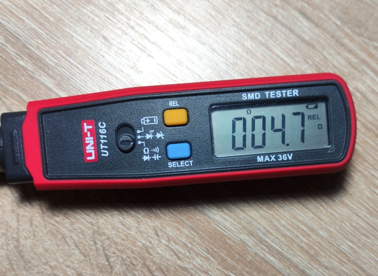
So letter “R” mean point or just “ohm”.
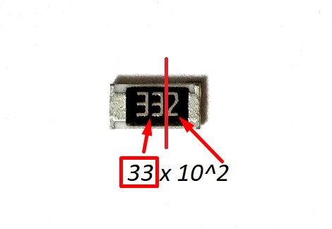
What about this?
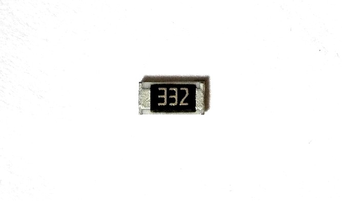
It’s simple, too 33 x 10^2 = 3300 ohm.
Let’s see if that’s true.
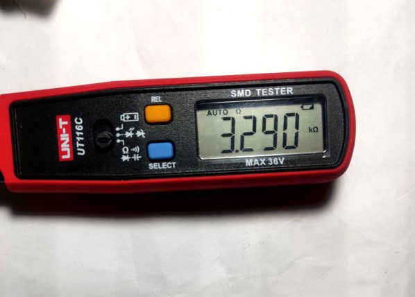
The same principle is used here. Both of these resistors are 10 kilohms.
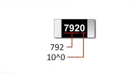
Don’t be alarmed if you see 4 digits. 792 х 10^0 = 792 ohm.
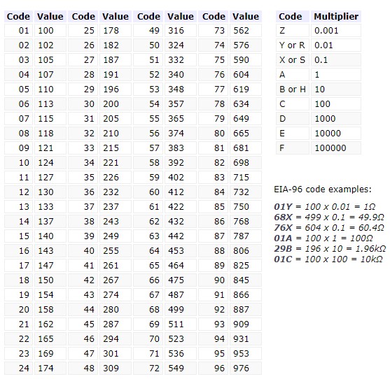
There is also another marking of SMD resistors that is very rare. It’s called EIA-96. It consists of a three character code: the first 2 numbers will tell us the 3 significant digits of the resistor value.
Video about resistors: