

First, let’s remember what are conductors and resistors? A conductor is a substance or some material that conducts electric current. Any conductor of electric current has some kind of resistance (except for superconductors). Therefore, any conductor can be thought of as a resistor that has resistance.
The resistance of a conductor can be found using the formula:

R – resistance, represented by the capital Greek letter omega (Ω) or “ohm”.
l – length of wire, m
ρ – resistivity, Ω⋅m
S – cross section area, m2
Resistor in series
Resistance of resistors in series
It’s pretty simple here.
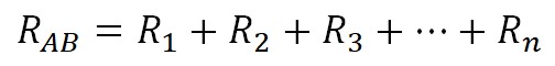
When resistors are connected in series, their total resistance is equal to the sum of the resistance of each resistor.
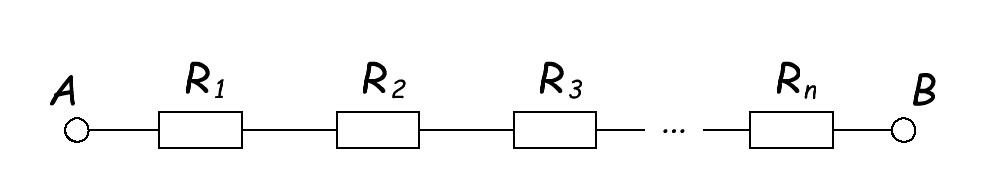
In our case, the resistance between points A and B will be equal to the sum of the resistances of each resistor.
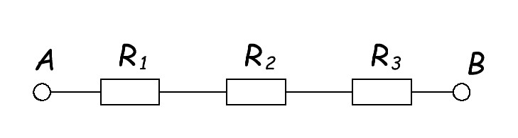
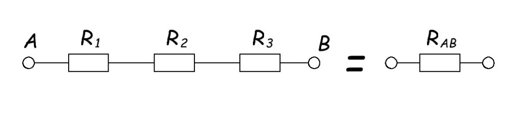
For example, we have three resistors that are connected in series. What will be the resistance between the points A and B?
R1 = 5 ohms, R2 = 3 ohm, R3 = 2 ohm.
Solution:
RAB = R1 + R2 +R3
RAB = 5 + 3 + 2 = 10 ohm
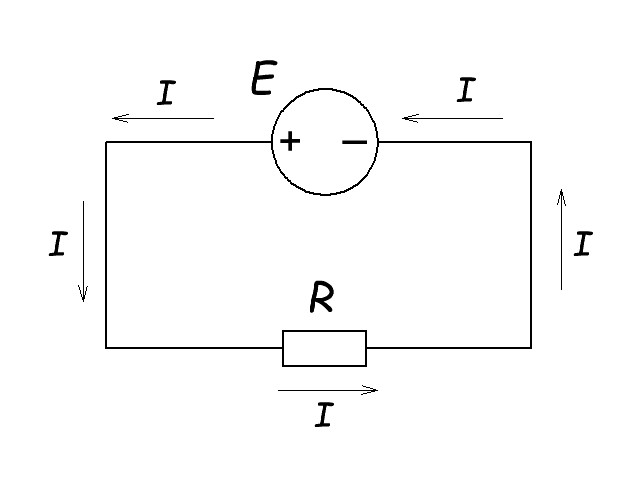
Current in Series Circuits
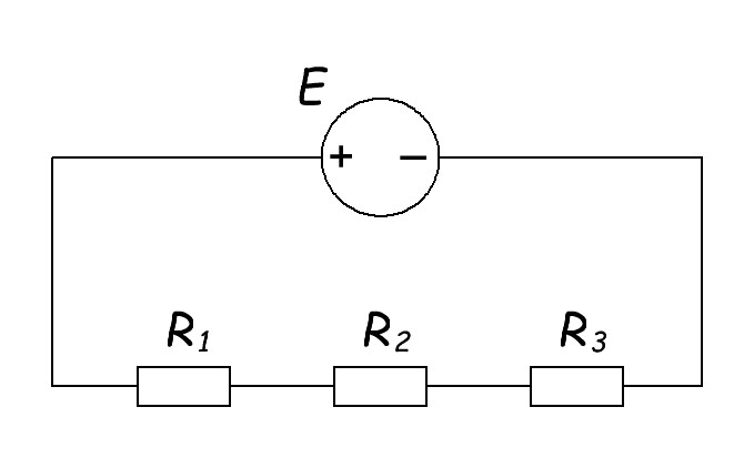
When radio elements are connected one after another – this is called series connection. For example, like this:
What happens if we connect a voltage source (EMF) to this circuit of resistors connected in series?
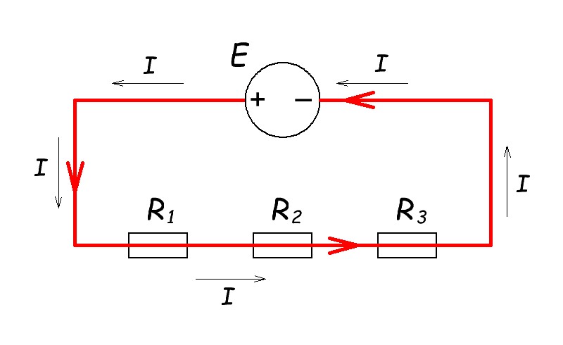
Current (I) will immediately start flowing in this circuit.
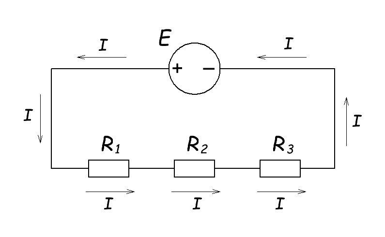
In a circuit where resistors or any conductors are connected in series, the current will flow the same everywhere. The current through resistor R1 will be the same rating as the current through resistor R2 and the same as the current through resistor R3. In fact, the current will be the same throughout the circuit, even in the wires that connect the resistors and the voltage source. And in resistors, too.
Example:
We have this electric scheme:
E = 10 V, R1 = 5 ohm, R2 = 3 ohm, R3 = 2 ohm.
What current (I) will flow in the circuit?
Solution:
First we need to calculate the total resistance in the circuit. We know the rule: when resistors are connected in series, their total resistance is equal to the sum of the resistance of each resistor.
R = R1 + R2 + R3
R = 5 + 3 + 2 = 10 ohm
Then we use Ohm’s law: I=U/R. In our case U=E.
I=10/10=1 A
Checking the simulation in an online programme Every Circuit:
Perfect!
Voltage in Series Circuits
So what happens to the voltage in this case?
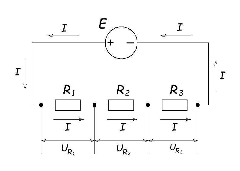
In this case, a voltage is created across the terminals of each resistor. It’s called “voltage drop.”
At the terminals of resistor R1 a voltage UR1 will appear. There will be voltage drop UR2 on resistor R2. We can also measure the voltage UR3 across resistor R3. But you know what’s interesting?
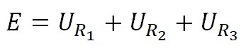
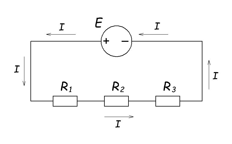
If we consider the general case for all circuits where resistors are connected in series, we get this picture and formula:
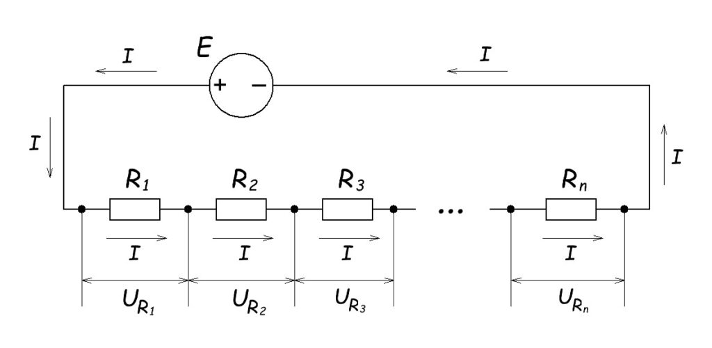
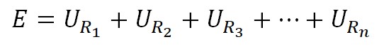
This formula is also called Kirchhoff’s second law.
Example.
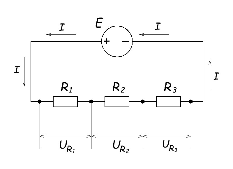
We have this scheme:
E = 10 V, R1 = 5 ohm, R2 = 3 ohm, R3 = 2 ohm.
What is the voltage drop across each resistor? So we need to find: UR1 , UR2 , UR3 .
Solution:
Above we found out what current will flow in the circuit.
I = U/(R1 + R2 + R3) = 10/10=1 A
Now how do we calculate the voltage drop across each resistor? Here we will again use Ohm’s law I=U/R, so U=IR.
UR1 = IR1 = 1 x 5 = 5 Volts
UR2 = IR2 = 1 x 3 = 3 Volts
UR3 = IR3 = 1 x 2 = 2 Volts
Let’s check if our task is solved correctly.
For this we will use Kirchhoff’s second law:
In our case: E = UR1 + UR2 + UR3
10 = 5 + 3 + 2
That’s right! This means that our task is solved correctly.
Checking the simulation:
Resistors in parallel
Resistance of resistors in parallel
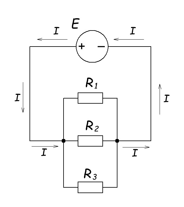
This is what a parallel connection of resistors looks like:
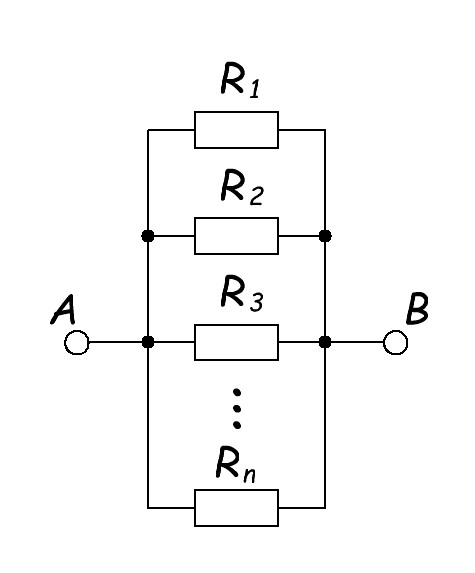
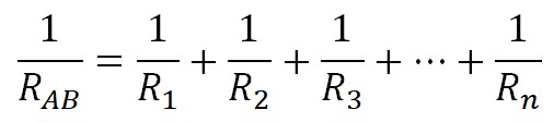
Calculating the resistance of resistors connected in parallel is a little more complicated than resistors connected in series. To find the total resistance, we need a formula:
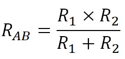
In practice, two resistors connected in parallel are the most common.
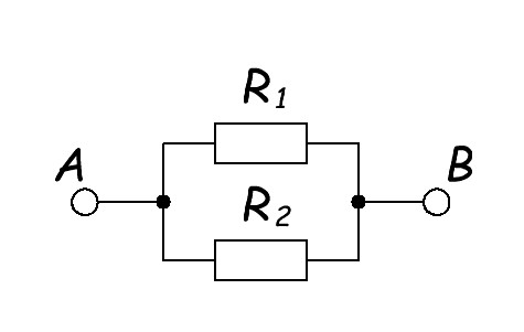
In this case their total resistance will be represented by the formula:
Voltage in parallel circuits
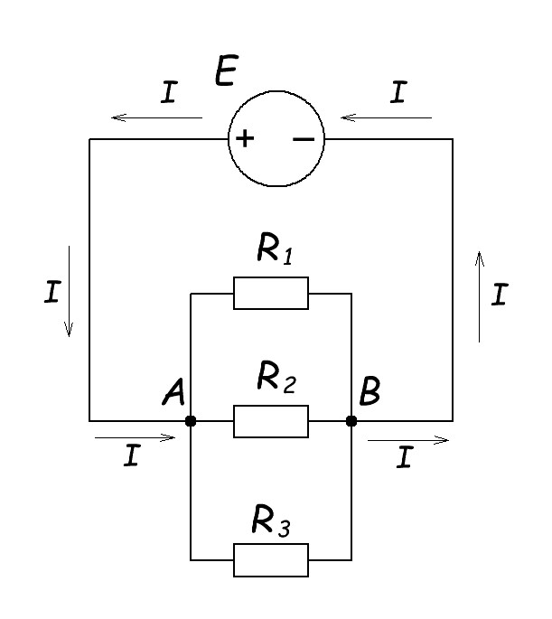
Let’s take a look at this circuit diagram:
What will be the voltage drop across resistor R1, R2, R3?
Point A and B receive voltage from a single voltage source E, and the leads of each resistor are connected to these points.
It doesn’t take much intelligence to realize that the voltage across the pins of each resistor will be the same: the power supply voltage. If you look at the circuit diagram, you can see that UAB=E=UR1=UR2=UR3 .
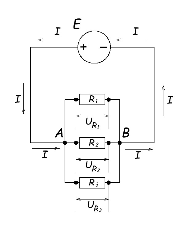
So, when the resistors are connected in parallel, the voltage drop across each resistor is the same.
Current in parallel circuits
Let’s look at our picture again.
What is the current that will flow through each resistor? Well you’ll say the same as in an electrical circuit and you’d be very wrong. But why? Ohm’s Law…
Ok, Let in our example:
E = 10 V, R1 = 10 ohm, R2 = 5 ohm, R3 = 2 ohm
It follows from Ohm’s law that we will have a different current flowing through each resistor. In the picture below you can see what current is flowing through each resistor.
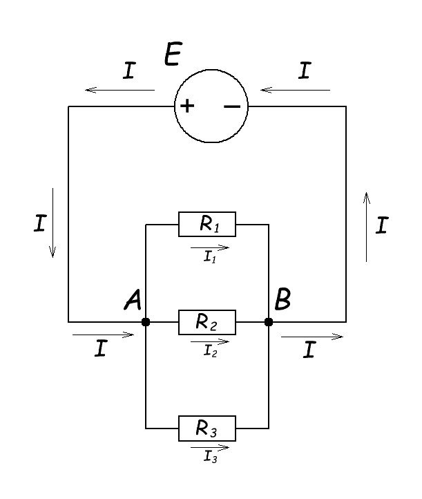
So, we already know that the voltage across all resistors is the same and equal to the voltage of the EMF source (E): E=UR1=UR2=UR3 . From Ohm’s law:
I1 = E/R1 = 10/10 = 1 A
I2 =E/R2 = 10/5 = 2 A
I3 = E/R3 = 10/2 = 5 A
So how do we calculate the current (I) flowing in a common circuit? Again we use the fundamental law of all electronics:
I=U/R
In this case:
U=E
I = E / (R1 || R2 || R3)
“||” means that our resistors are connected in parallel.
How do you find the resistance of three resistors connected in parallel?
We have to use the formula:
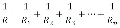
Since we have only three resistors connected in parallel, their resistance will be expressed by the formula:
1/R = 1/R1 + 1/R2 + 1/R3
1/R = 1/10 + 1/5 + 1/2
1/R = 0,8
R = 1/0,8 = 1,25 ohm
I = E/R = 10/1,25 = 8 A
But the interesting thing is that we have a total current equal to the sum of the currents in each of the resistors.
Let’s check:
I = I1 + I2 + I3
8 = 1 + 2 + 5
Perfect!