Let’s agree at once: in our article the word “current” we will mean the “intensity of current”.
- Hydraulic analogy
- What is the current
- Current formula
- What about AC current
- How to measure DC current
- Measuring with a laboratory power supply
- Measuring with a multimeter
- Measuring with a shunt
- Measuring with a clamp meter
- How to measure AC current
- Measuring AC with a multimeter
- Measuring AC with a clamp meter
Hydraulic analogy
So we have a water tower.
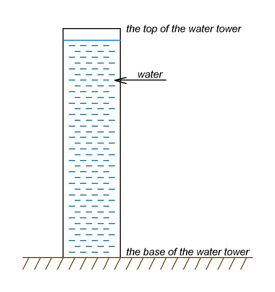
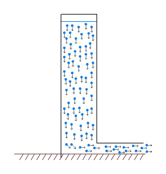
As you know from the last article about voltage, the volume of water presses on the bottom of the water tower. What happens if we make a hole at the bottom of the water tower and connect a water pipe? Water will flow from the water tower through the water pipe.

Let’s connect two pipes of different diameters to the bottom of our water tower instead of one pipe (top view).
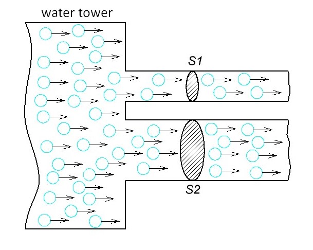
Through which pipe will more water pour out in one second given the fact that they are at the same height from the bottom of the tower? I think it’s thick pipe. It is obvious.
If you cut the pipes at a right angle, then we will see the cross-sectional area. S1 – cross-sectional area for small pipe. S2 – cross-sectional area for thick pipe. S1<S2. For some equal period of time trough S1 fewer water molecules will pass than S2.
Let’s look at another example. We have two garden hoses. Their diameters are the same, and therefore the cross-sectional area is the same. But one of them has a strong water flow, and the other has a weak water flow.
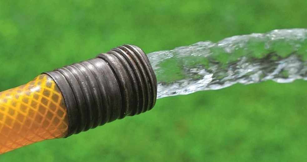
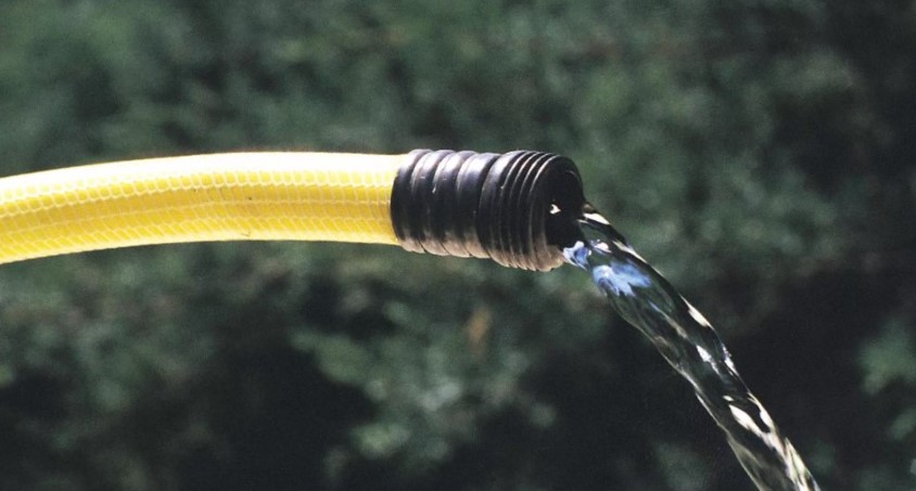
Now imagine that you are filling a bucket. With the water pressure from which hose will you fill it faster? Of course, the one with the stronger water pressure. In an equal period of time, more water molecules will pass through the cross-sectional area of the orange hose than through the cross-sectional area of the yellow hose.
What is the current
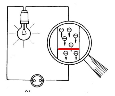
Almost all the same paragraph above we can apply to electronics. By analogy with hydraulics, a wire is a garden hose, water molecules are electrons.
Let’s look at a simple copper wire. The area of the cross-sectional area of this wire is shaded in green.
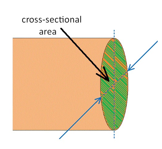
The more electrons pass through this green shaded area in one second, the more current will be in this wire.
Current formula
What will the formula look like?
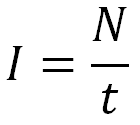
I – current, A (Ampere)
N – number of electrons
t – the period of time for which these electrons will run through the cross section area of the conductor, s (seconds)
A more correct (official) formula looks like this:
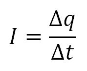
I – current, A (Ampere)
Δq – is the electric charge over a certain period of time, C (Coulomb)
Δt — time interval, s (seconds)
What is the point of these two formulas? The thing is that the electron has a charge of approximately 1,6·10-19Coulomb. Therefore, in order for the current strength in the wire (conductor) to be 1 Ampere, we need a charge of 1 Coulomb = 6,24151⋅1018 electrons to pass through the cross section.
1 Coulomb = 1 Ampere х 1 second
So, now we can officially say that if 6,24151⋅1018 electrons fly through the cross section of the conductor in 1 second, then the current in this conductor will be equal to 1 Ampere!
What about AC current
Our previous conversation was about direct electric current (DC current), in which electrons move in only one direction. So what about the AC current? We know differences between AC and DC current.

As you know AC current look like this:
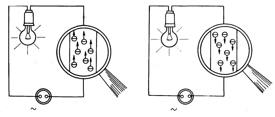
First the electrical current flows in one direction, then it slows down and starts to flow in the other direction.
It’s like a baby swing.

Current for AC current interprets the same. The cross section of the conductor electrons can cross on either side. In our example, first from the bottom up:
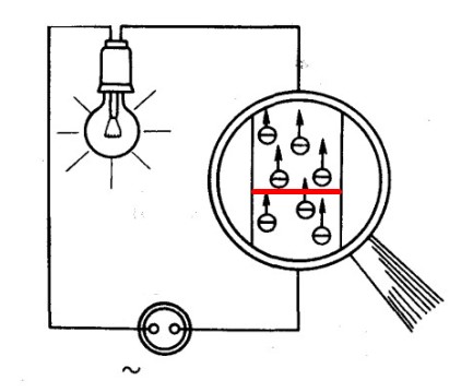
and then down
How to measure DC current
Measuring with a laboratory power supply
This is the easiest way if you have a laboratory power supply.
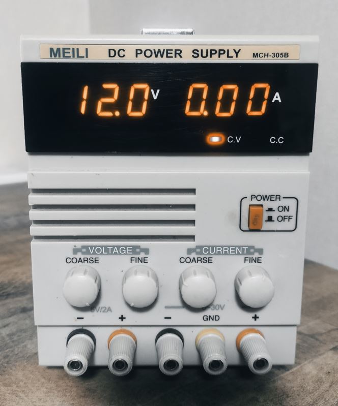
It will immediately give you current value on its display.
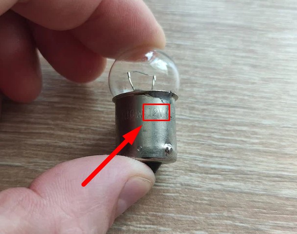
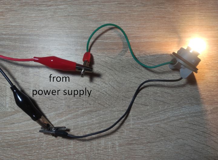
Let’s find out the current that’s flowing through the lamp. We have a 12 volt lamp.
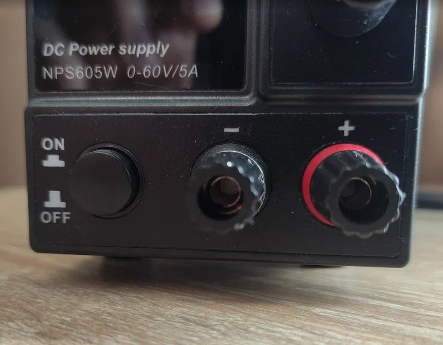
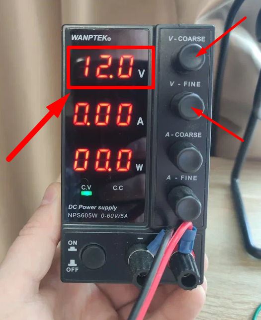
And a laboratory power supply like this:
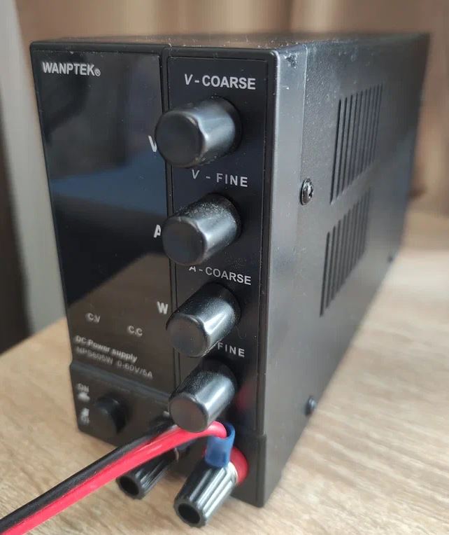
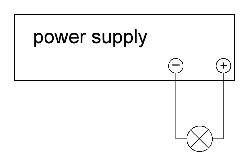
Each DC power supply has two outputs: plus and minus. Most often, the plus is red, and the minus is black.
Most often, two crocodile probes are attached to the power supply.
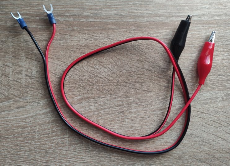
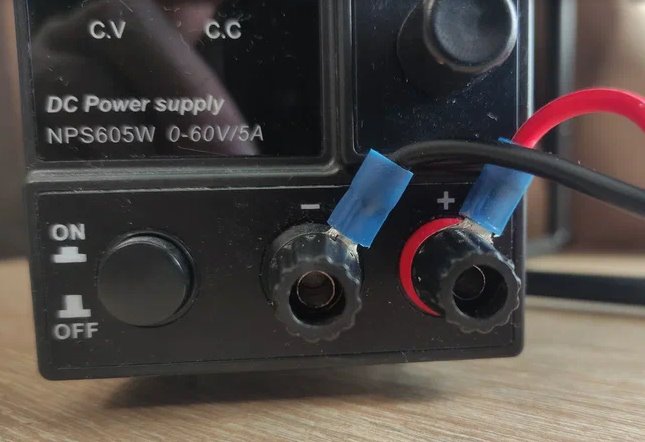
These two probes are connected to the power supply terminals.
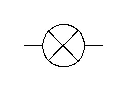
Ok, the lamp on the diagram is marked like this:
And here’s the schematic for connecting the lamp to the power supply:
Since our lamp has a rated voltage of 12 volts, we will supply it with 12 volts. Set voltage 12 volts.
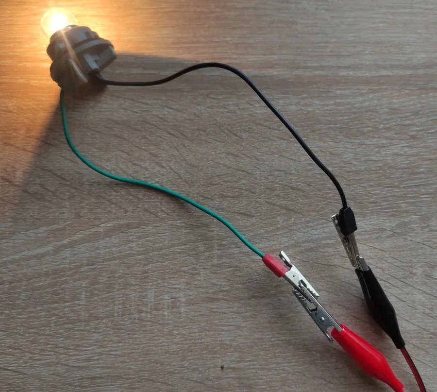
Connecting the lamp to the wires. Wow, the lamp is glowing!
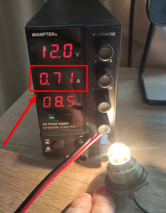
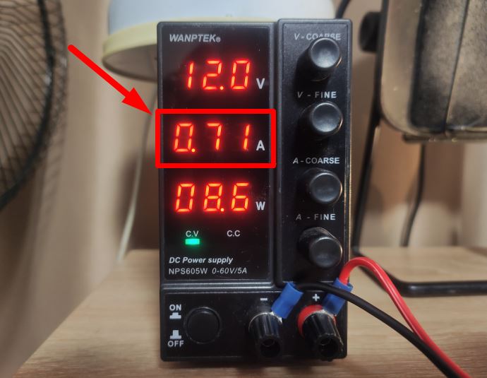
Let’s take a look at the power supply display. On the display we see a value of 0.71 A. This tells us that the 0.71 A current is passing through the light bulb.
Any other load can replace the lamp.
Measuring with a multimeter
The most important rule when measuring with a multimeter is to connect the multimeter to the break of the measured circuit. Here’s an example of how you can measure the current in a circuit with a multimeter.
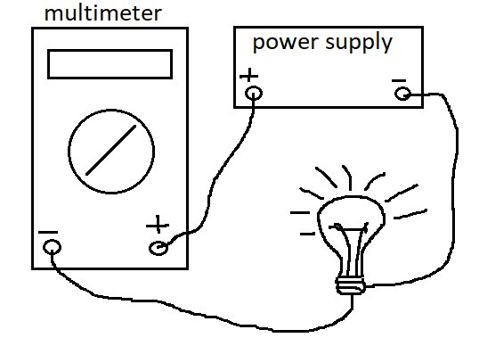
Let’s look at this in practice. We’ll need a multimeter, a power supply and a bulb.
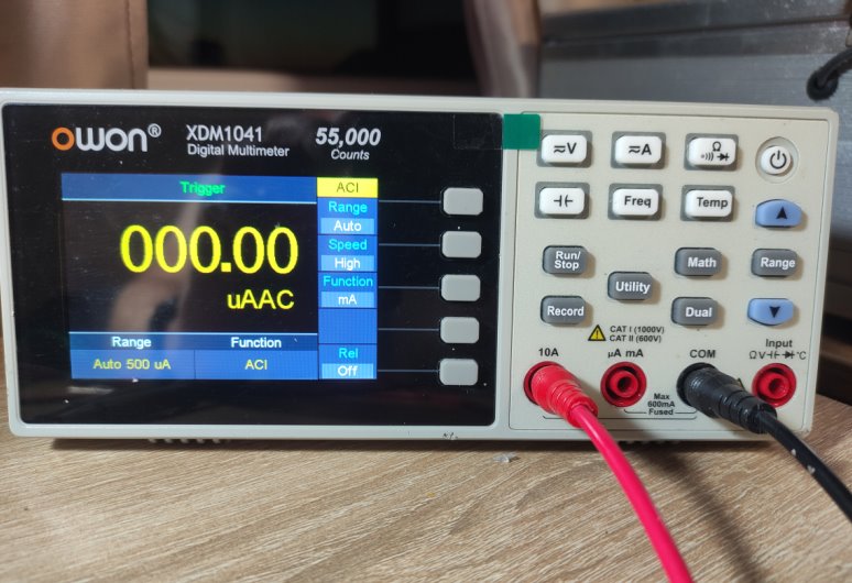
My multimeter:
Push this button:
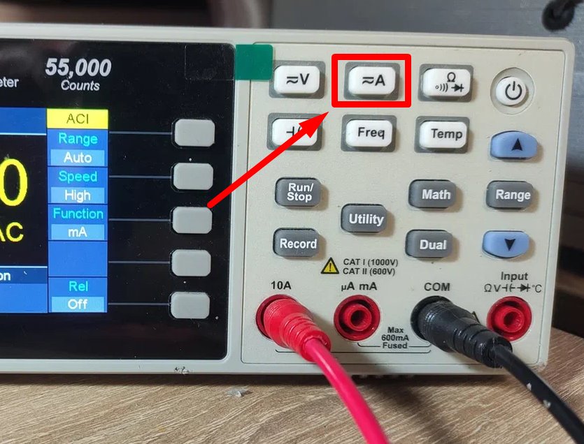
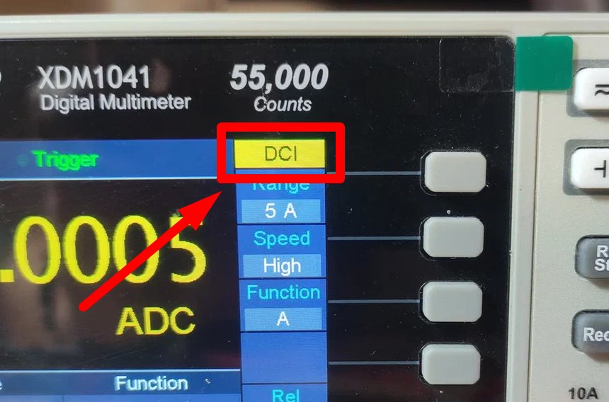
We must see the sign DCI which means Direct Current I
In order to measure the current, we must insert a red probe into the socket that measures the current.
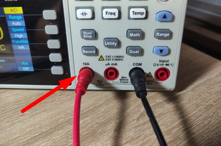
Use connection diagram
and see the result
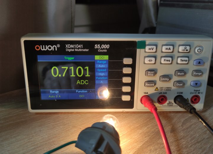
This is the same result we saw on the power supply: 0.71A
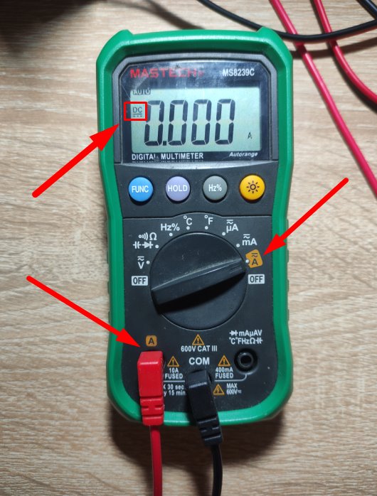
If you have a simple multimeter, then here we do all the same. In order to measure the DC current, we have to put a pointer on the ~=A icon. Next, use the FUNC button to select the =DC icon. Almost the same steps we took when measuring DC voltage.
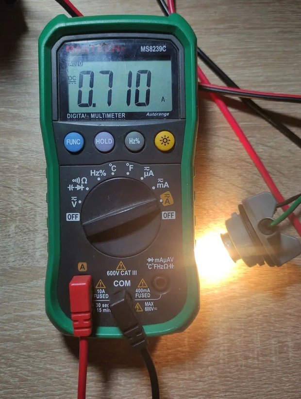
So here’s the result:
Measuring with a shunt
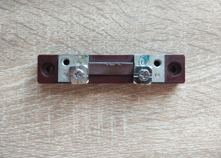
Let’s assume that you only have a voltmeter. How do you measure current with a voltmeter? To do this, we will need an electric shunt. I have one. He looks like this:
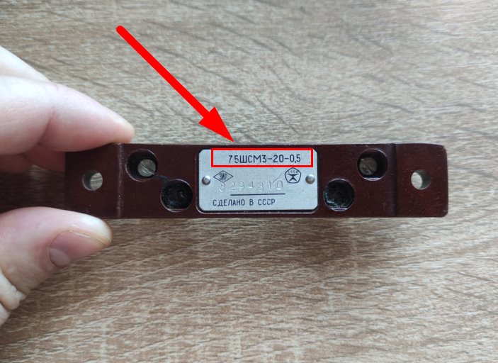
You can see its markings on the back. This shunt was made in USSR so it has specific marking. If the voltage drop on the shunt is 75 mV, then a current of 20 amperes passes through it. 0.5 – the error in percentage.
On modern shunts we can see such marking.
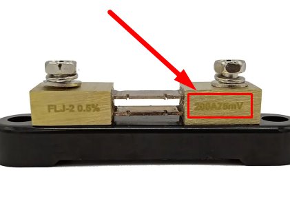
If the voltage drop on the shunt is 75 mV, then a current of 200 amperes passes through it. 0.5% – the error in percentage. That’s easy!
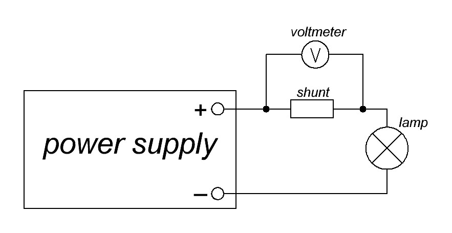
The typical shunt circuit looks like this:
So, all we need to do is measure the voltage drop on the shunt itself and to solve a simple equation. Go!
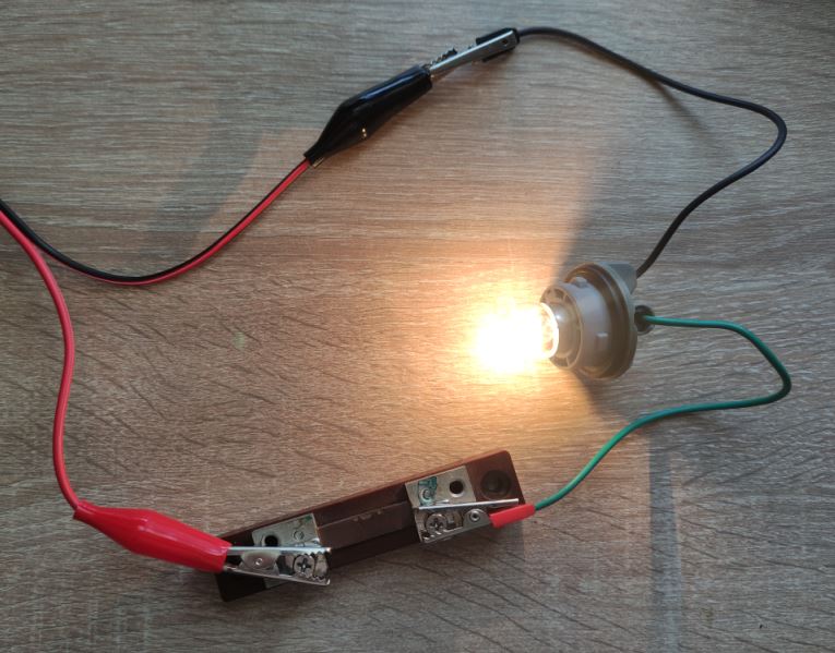
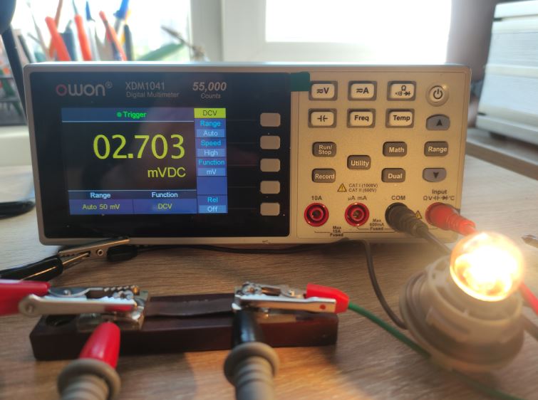
Next, we measure the voltage drop on the shunt.
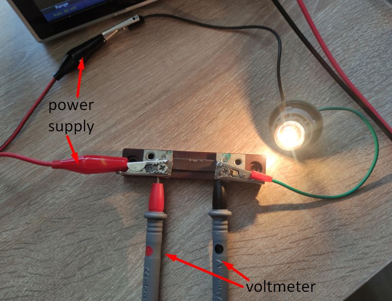
So on the shunt the voltage drop is 2.7 mV
We already know that if the voltage drop on the shunt is 75 mV, then the current through the shunt will be 20 amps. This is a linear dependence. Let’s solve the equation:
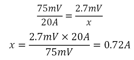
So 0.72 A will be the current in the circuit of lamp.
Compare to our past records

Error 0.01 A !
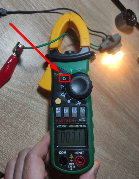
Measuring with a clamp meter
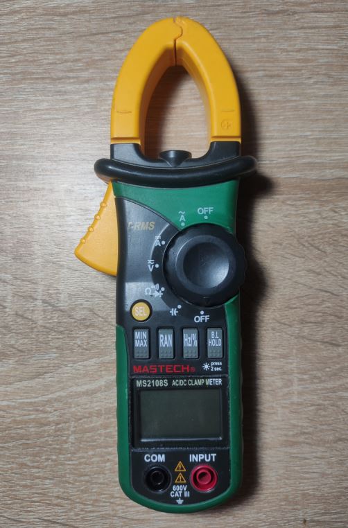
I have a clamp meter that can measure the current without breaking the circuit. A very convenient and practical device. So, let’s connect the light bulb to the power supply.
As you remember, my lamp consumes 0.71 amps
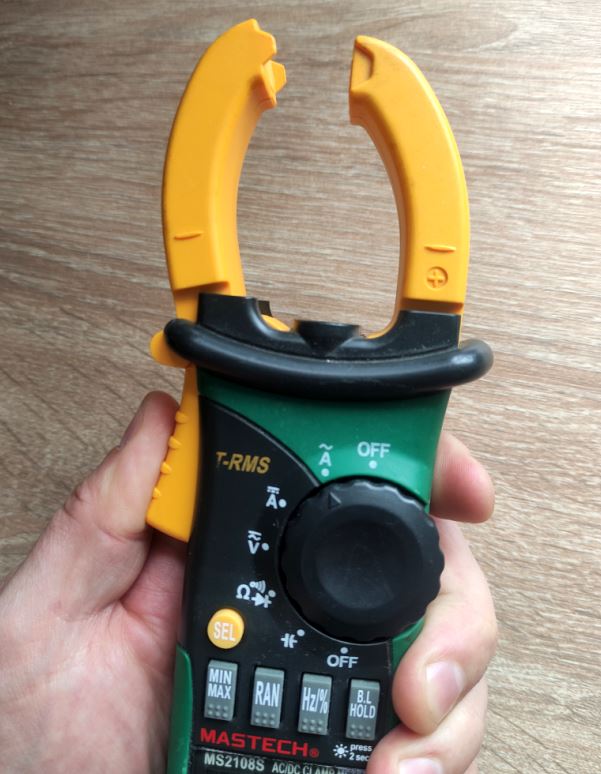
Let’s check with a clamp meter. Clamp meter are convenient because you do not need to break the circuit. Enough to grab the wire.
How to measure AC current
Measuring AC with a multimeter
I think every multimeter can measure the AC current. It is enough to switch the measurement mode from DC to AC by a functional button. ACI mean Alternating Current I .
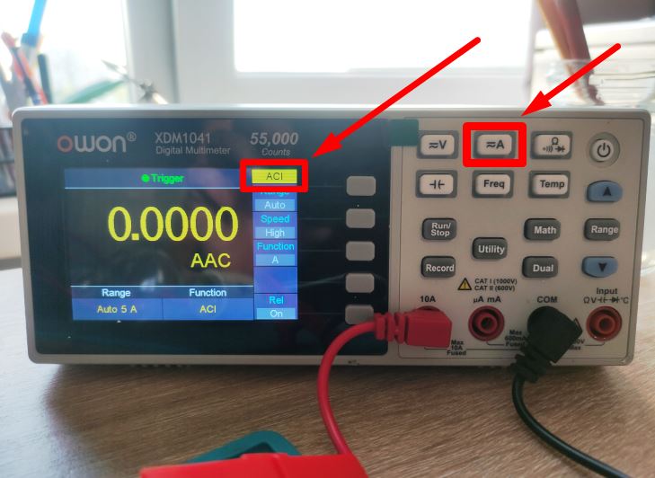
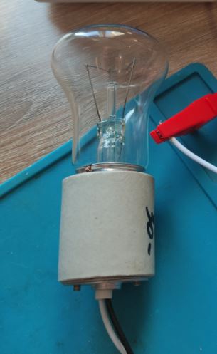
I have a lamp. This lamp is 90 watt. Voltage is 220 V. So P=IU, I=P/U=90/220=0,4 A. Let’s see what the multimeter will show us.
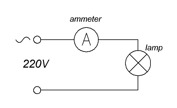
connect the light bulb and the ammeter according to this scheme
Looking at the display of the multimeter.
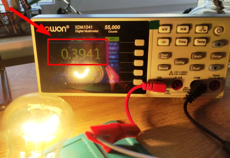
0,3941 A. That’s very close to the calculation above.
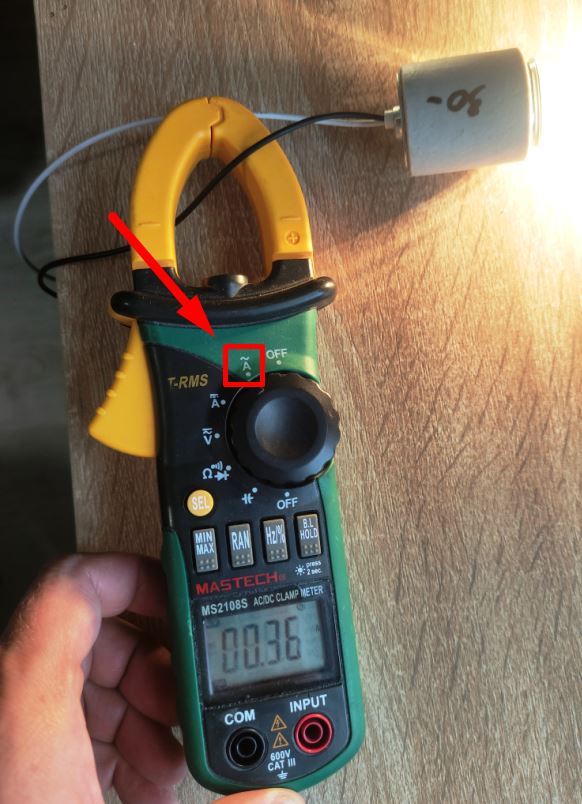
Measuring AC with a clamp meter
In order to measure the alternating current, we must set the runner on “AC~” and then wrap the wire with clamp meter. On the display we see a value of 0.36 A. Comparing this value to the multimeter, the error is 0.03 A. It’s a good result.
To learn more, click on the video